Control Unit For Controlling An Engine Stop Of A Hybrid Vehicle

a control unit and hybrid technology, applied in the direction of engine-driven generators, machine/engine control, process and machine control, etc., can solve the problems of affecting the quality of driving, disengagement, etc., and achieve the effect of minimizing any unnecessary fuel consumption and unnecessary fuel consumption

Active Publication Date: 2008-03-20
NISSAN MOTOR CO LTD
View PDF23 Cites 46 Cited by
  • Summary
  • Abstract
  • Description
  • Claims
  • Application Information

AI Technical Summary

Benefits of technology

[0009] In another example, the HEV control system selects an appropriate mode transition pattern from a plurality of mode transition patterns upon considering the driving force selected by the driver when the hybrid drive mode is changed to the electric drive mode. For example, when the change in the driving force is only slight, defueling the engine may cause a sudden shock to the vehicle, which may make the driver feel uncomfortable. Therefore, a mode transition pattern for disengaging the first clutch prior to engine defueling is selected to prevent such a shock from occu...

Problems solved by technology

However, when switching from the hybrid drive mode to the electric drive mode, the order betw...

Method used


Image

  • Control Unit For Controlling An Engine Stop Of A Hybrid Vehicle
  • Control Unit For Controlling An Engine Stop Of A Hybrid Vehicle
  • Control Unit For Controlling An Engine Stop Of A Hybrid Vehicle

Examples


Embodiment Construction

[0025] The control unit of the present invention will be fully discussed below in view of the provided figures.

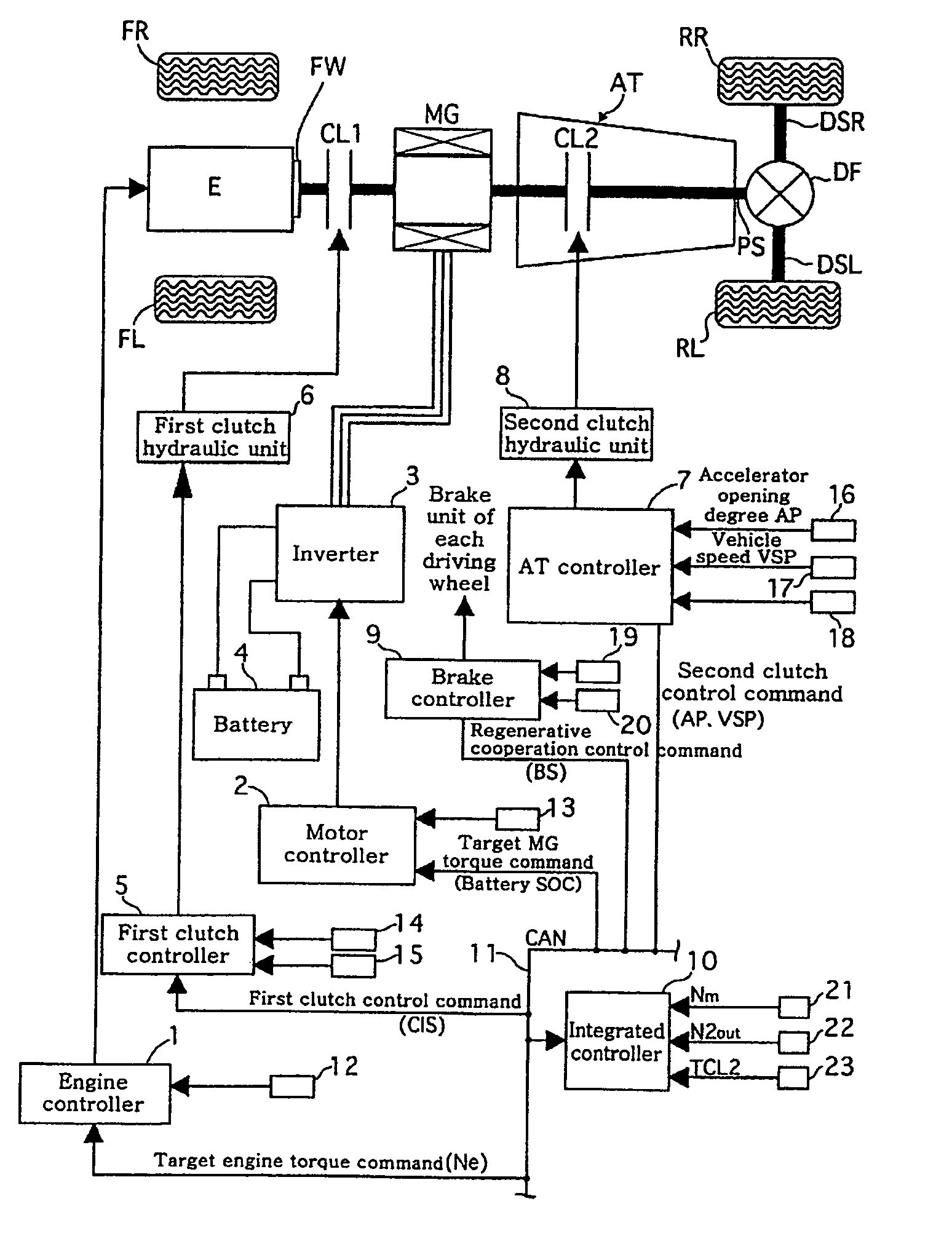
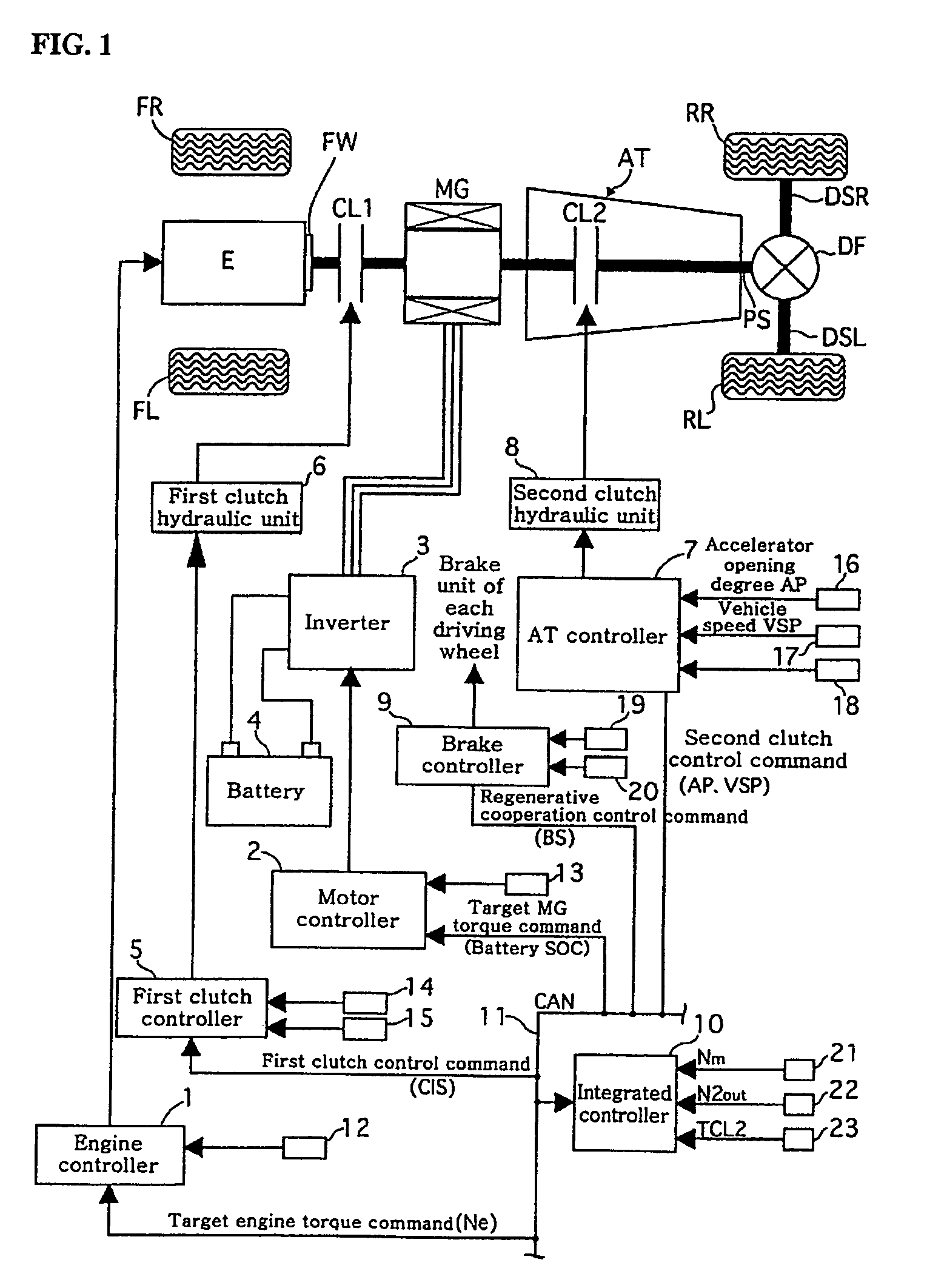
[0026]FIG. 1 is a block diagram illustrating a rear-wheel drive hybrid vehicle having a control unit for controlling an engine stop in accordance with a preferred embodiment of the present invention.

[0027] As shown in FIG. 1, a hybrid vehicle driveline includes an engine E, a flywheel FW, a first clutch CL1, a motor / generator MG, a second clutch CL2, an automatic transmission AT, a propeller shaft PS, a differential gear DF, a left-side driving shaft DSL, a right-side driving shaft DSR, a left-side rear wheel RL (driving wheel) and a right-side rear wheel RR (driving wheel).

[0028] The left-side front wheel is denoted as FL, whereas the right-side front wheel is denoted as FR.

[0029] The engine E is an internal combustion engine, such as a gasoline or diesel engine. Further, the opening of a throttle valve can be controlled based on a control command from an engine contro...


PUM


Abstract

A hybrid vehicle control system for cutting off fuel to an internal combustion engine of hybrid vehicle while providing smooth transitions from a hybrid drive mode to an electric drive mode is provided. The hybrid vehicle control system includes an integrated controller configured to receive inputs corresponding to vehicle speed and an indicated driving force, and to select an appropriate mode transition pattern from a group of mode transition patters according to the change in indicated driving force.

Description

CROSS-REFERENCE TO RELATED APPLICATIONS [0001] This application claims priority under 35 U.S.C. § 119 to Japanese Patent Application No. 2005-357078 filed on Dec. 12, 2005. The entire disclosure of Japanese Patent Application No. 2005-357078 is hereby incorporated herein by reference. TECHNICAL FIELD [0002] The present invention relates to a hybrid vehicle control system for decreasing or cutting off the fuel (hereinafter referred to as “defueling” or “stopping” the engine) to an internal combustion engine of a hybrid vehicle. In particular, the hybrid vehicle control system coordinates engine defueling with other driveline operations to ensure a smooth transition from a hybrid drive mode to an electric drive mode. BACKGROUND OF THE INVENTION [0003] The term “hybrid vehicle” typically refers to a vehicle that has both internal combustion and electric motor propulsion. In a conventional hybrid vehicle, a first clutch is installed between an internal combustion engine and an electric ...

Claims


Application Information

Patent Timeline
IPC IPC(8): B60L15/20B60K6/48B60K6/54B60K6/547B60L50/16B60W10/02B60W10/04B60W10/06B60W10/08B60W20/00F02D17/00F02D29/00F02D29/02F02D41/04F16D48/02
CPCB60K6/48Y10S903/906B60W10/02B60W10/06B60W10/08B60W10/10B60W20/00B60W2510/244B60W2710/027B60W2710/0666B60W2710/083Y02T10/6221Y02T10/6286Y02T10/642Y02T10/7258Y02T10/48Y10T477/70Y10T477/23Y10T477/26Y10T477/759Y10T477/24Y10S903/902Y10S903/903Y10S903/905B60L2240/423B60L15/2054B60L2240/443B60L2240/507Y02T10/72B60L50/16Y02T10/40Y02T10/62Y02T10/64Y02T10/7072B60W20/11B60W20/40Y02T10/70
Inventor HIRATA, TAKESHIYAMANAKA, TSUYOSHIKANEKO, HIROSHI
Owner NISSAN MOTOR CO LTD
Why Eureka
Try Eureka