Control device for an internal combustion engine of a vehicle

a control device and internal combustion engine technology, applied in the direction of machines/engines, registering/indicating working of vehicles, etc., can solve the problems of fuel waste, delay in determining whether the regenerating operation should be continued, and difficult to detect the change in the temperature of exhaust gas, so as to avoid unnecessary fuel consumption and accurate account

Inactive Publication Date: 2008-02-14
HONDA MOTOR CO LTD
View PDF4 Cites 12 Cited by
  • Summary
  • Abstract
  • Description
  • Claims
  • Application Information

AI Technical Summary

Benefits of technology

[0010]Thus, when a loading device is activated and the exhaust gas temperature is high, the regeneration operation is continued even when the vehicle speed is relatively low and the DPF is thereby more actively regenerated.
[0011]The loading device may comprise an air conditioner. The congestion threshold value can be most conveniently given as a vehicle speed threshold. If the vehicle speed threshold is varied depending on a shift position of a transmission system of the vehicle, typical operating modes of the vehicle in a congested state such as traveling at a relatively high speed in a low gear can be accurately accounted for.
[0012]According to a preferred embodiment of the present invention, the vehicle is provided with a temperature sensor for detecting a temperature of the particulate filter, and the control unit continues the regeneration process even when a congested state is detected if a detected temperature is higher than a prescribed value. Thereby, the regeneration operation of the engine is carried out whenever possible. However, if the temperature of the particulate filter cannot be raised to the combustion temperature of the particulate matter such as diesel emitted particulate matter even with a post injection or other measures, the regeneration operation is suspended and unnecessary consumption of fuel can be avoided.

Problems solved by technology

Furthermore, even when a post fuel injection is carried out, it may not be possible to raise the temperature of the DPF to the combustion temperature of the DEP, and this leads to a fuel waste.
However, the method of Japanese patent laid open publication Number 2001-161044 relies on the temperature of the DPF in determining if the regenerating operation may be continued, it is difficult to detect the changes in the temperature of the exhaust gas.
In other words, because the regeneration of the DPF occurs only after the temperature of the exhaust gas has reached the combustion temperature of the DEP, it is inevitable to have a delay in determining whether the regenerating operation should be continued in relation to the changes in the temperature of the exhaust gas.
Also, because a oxide catalytic converter is provided upstream of the DPF, it is not possible to account for the activity level of the oxide catalyst when determining the temperature of the DPF.
According to the method of Japanese patent laid open publication Number 2000-132223, because the regenerating operation is unconditionally suspended in a congested road condition, even when the exhaust gas temperature rises owing to the activation of a loading device (such as a compressor of an air conditioner), the frequency of regenerating the DPF becomes undesirably low particularly when the vehicle is traveling in a rural area so that the resulting pressure loss of the exhaust gas may cause a reduction in the engine output.
Also, because the congested state of the road is determined solely from an output of a vehicle speed sensor, depending on the selection of the threshold level, some of the typical operating modes of the vehicle in a congested state such as traveling at a relatively high speed in a low gear may not be properly accounted for.

Method used


Image

  • Control device for an internal combustion engine of a vehicle
  • Control device for an internal combustion engine of a vehicle
  • Control device for an internal combustion engine of a vehicle

Examples


Embodiment Construction

Structure of the Embodiment

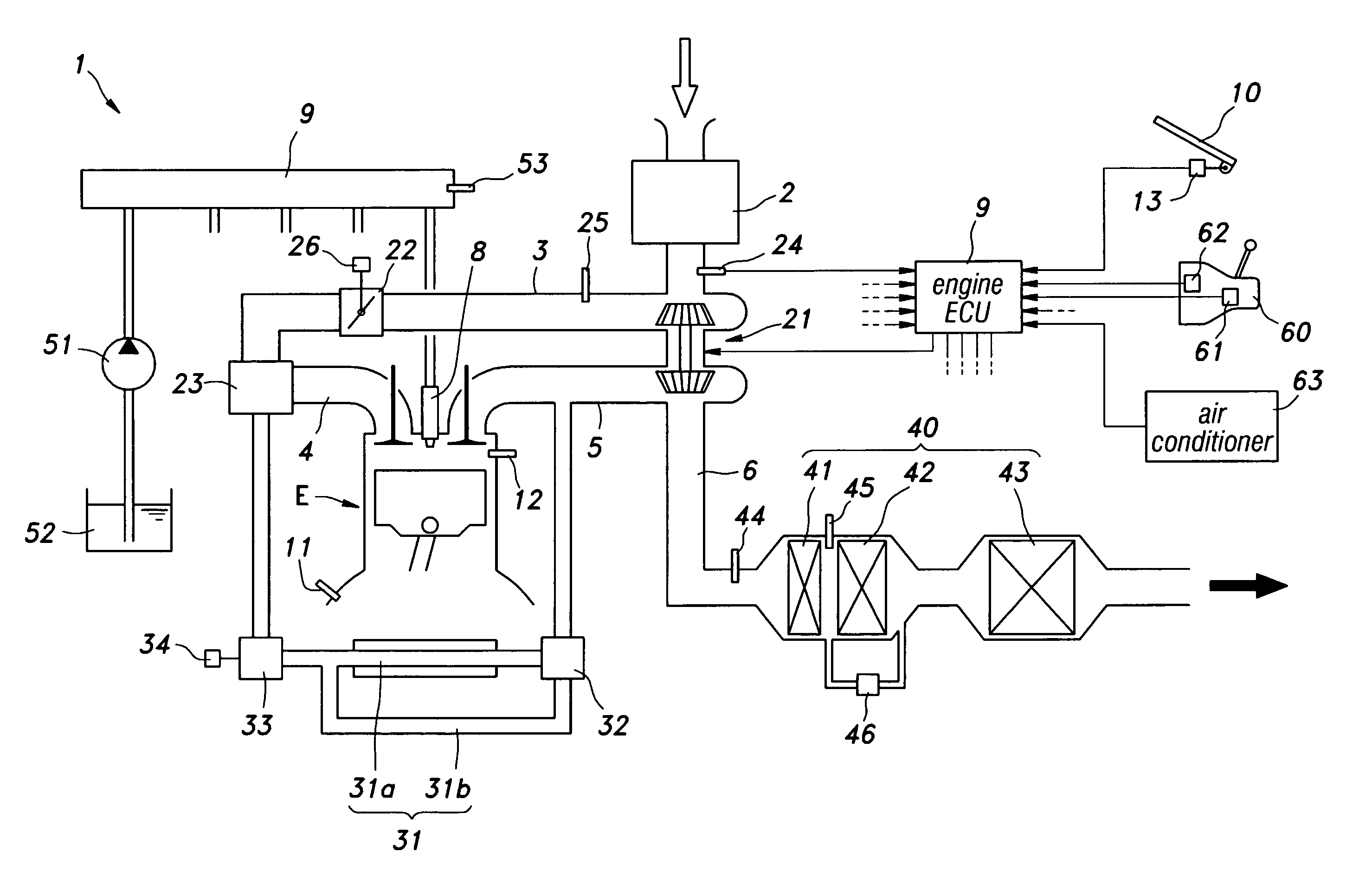
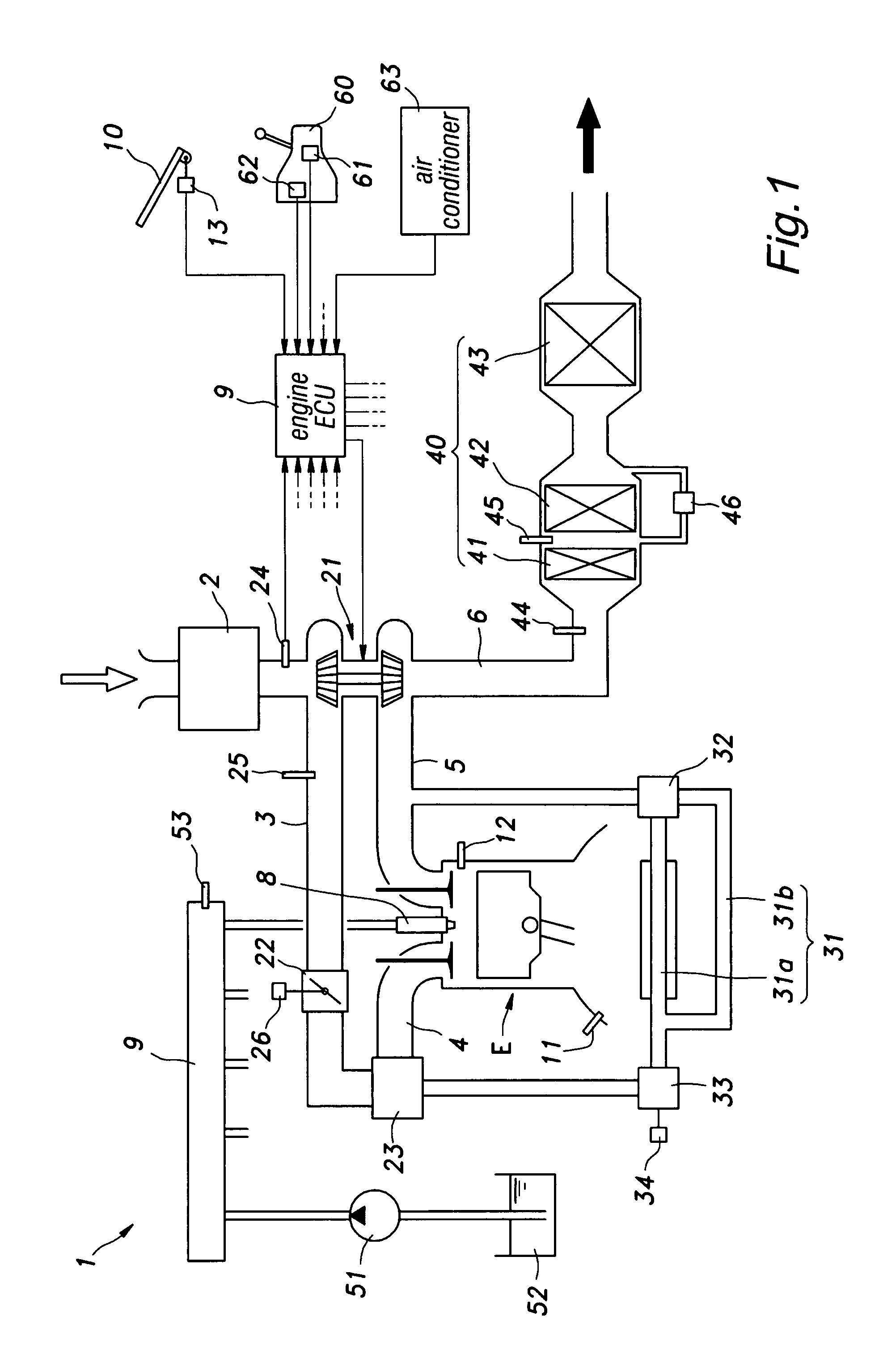
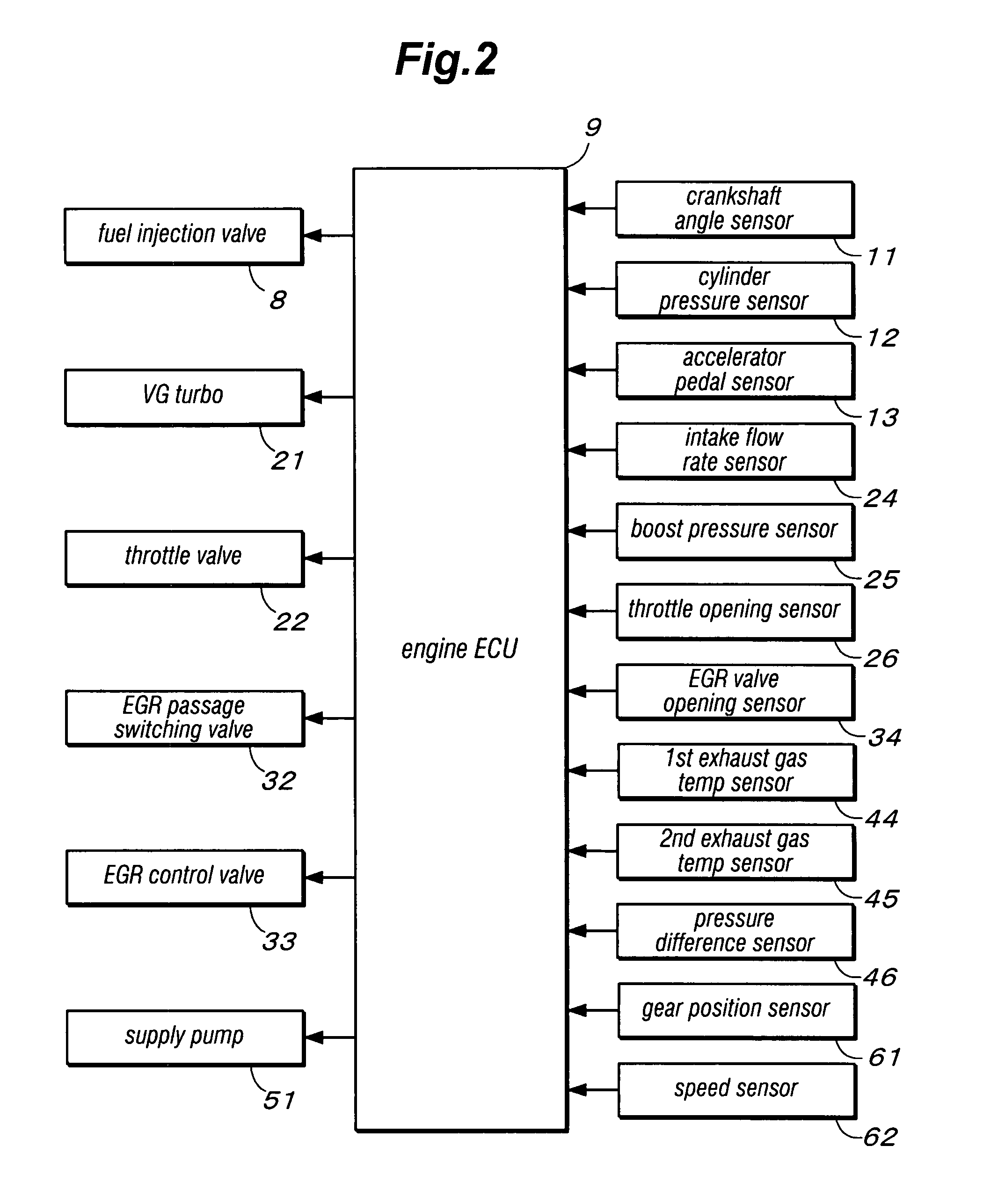
[0018]Referring to FIG. 1, the engine system 1 comprises a diesel engine (referred to simply as engine hereinafter) E and associated systems such as an intake system including an air cleaner 2, an intake pipe 3 and an intake manifold 4, an exhaust system including an exhaust manifold 5 and an exhaust pipe 6, and a fuel system including a common rail 7 and an electronically controlled fuel injection valve 8. In the illustrated embodiment, an engine ECU (electronic control unit) for controlling the engine system 1 as a whole is provided in a passenger compartment, and an accelerator pedal 10 is provided in front of a driver's seat for a vehicle operator to actuate. The engine E is provided with a crankshaft sensor 11 for detecting the crankshaft angle thereof and a cylinder pressure sensor 12 for detecting the pressure in the cylinder. The accelerator pedal 10 is provided with an accelerator pedal sensor 13 for detecting the depressing stroke of the accelera...


PUM

PropertyMeasurementUnit
combustion temperatureaaaaaaaaaa
temperatureaaaaaaaaaa
speedaaaaaaaaaa

Abstract

In a control device for an internal combustion engine (E) of a vehicle comprising a particulate filter (42) installed in an exhaust passage of the engine and a loading device (63) that applies a load to the engine, the control device (9) is configured to execute a regeneration process for regenerating the particulate filter under a prescribed condition. When a vehicle is in a congested state, the temperature of the particulate filter typically drops below a threshold level for enabling a regenerating process. However, according to the present invention, the particulate filter may be regenerated even when the vehicle is in a congested state if a loading device such as an air conditioner is activated, and the temperature of the particulate filter is therefore high enough. Thereby, the particulate filter may be actively regenerated whenever possible.

Description

TECHNICAL FIELD[0001]The present invention relates to a control device for an internal combustion engine of a vehicle, and in particular to a technology that allows a particulate filter to be favorably regenerated.BACKGROUND OF THE INVENTION[0002]A diesel engine emits a substantial amount of diesel emitted particulates (DEP) along with normal exhaust gas owing to incomplete combustion of fuel in diffusion combustion stage and delayed combustion stage. Therefore, a vehicle powered by a diesel engine is increasingly more often fitted with a diesel particulate filter (DPF) in an exhaust passage thereof to capture the EDP contained in the exhaust gas. As a practical DPF is known a wall flow type DPF which includes a cylindrical honeycomb structure made of porous ceramic material and having passages blocked in an alternating manner so that the exhaust gas may pass through the thin walls of the honeycomb structure and DEP may be captured in the process.[0003]In such a diesel engine, becau...

Claims


Application Information

Patent Timeline
Patent Type & Authority Applications(United States)
IPC IPC(8): F01N3/00
CPCF02D41/029F02D2041/026F02D41/083
Inventor CHIBA, ISAOTAKEUCHI, HIROTO
Owner HONDA MOTOR CO LTD
Why Eureka
Try Eureka