
Method and system to invert tectonic boundary or rock mass field in in-situ stress computation

Inactive Publication Date: 2008-03-20
SCHLUMBERGER TECH CORP
View PDF11 Cites 47 Cited by
  • Summary
  • Abstract
  • Description
  • Claims
  • Application Information

AI Technical Summary

Benefits of technology

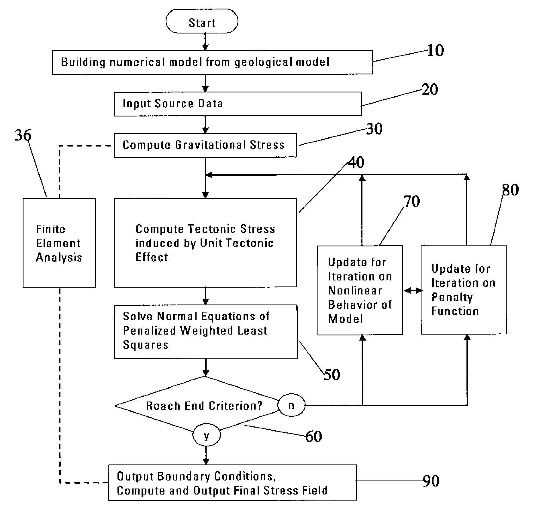
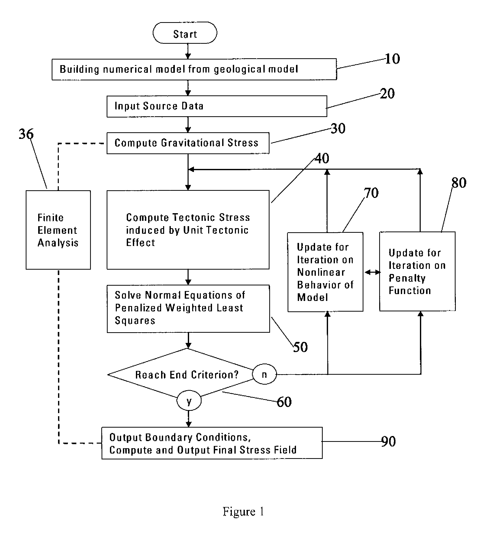
[0010]A first aspect of the invention is directed to a method to invert boundary conditions for rock mass field in-situ stress computation for a geologic structure, the method comprising the following steps: a) building a numerical model from a geological model of the geologic structure; b) inputting source data measured from the geologic structure into the numerical model; c) computing gravitational stress of the geologic struct

Problems solved by technology

However, how to invert the loading boundary from the measured data and field information is still one of the most difficult issues in the industry.
One of the big challenges for in-situ stress modeling comes from the complexity of in-situ stress itself.
Furthermore, the mechanical erosions and thermal histories of the site under investigation may be complex, leading to additional loading path dependent sources of distortion of the in-situ stress field.
Currently there are a few ways to approach the issue, but those ways have their own limitation.
For example, “Integrated Stress Determination Approach” relies on a nonlinear least squares approach to determine the regional stress field based on local stress measurement, but the strong assumptions involved in the ISDA method, such as neglecting the lateral variations of stress and the rotation of the principal stress direction, restrain this model applicability in complex geological conditions.
However this approach is based on the mathematical optimization theory and doses not include the complex geological mechanisms in the model.
However, the uniform boundary conditions assumed in the model can not meet the requirement of complex geological conditions.
However, same as F. Tonon's approach, McKinnon uses the uniform far-field boundary conditions, which is not the case for most geological structures

Method used


Image

  • Method and system to invert tectonic boundary or rock mass field in in-situ stress computation
  • Method and system to invert tectonic boundary or rock mass field in in-situ stress computation
  • Method and system to invert tectonic boundary or rock mass field in in-situ stress computation

Examples


Embodiment Construction

[0018]This invention develops a new technique to invert the boundary conditions for rock mass field in-situ stress computation. The proposed inverting procedure is based on the physical assumption that the in-situ stress can be decomposed into gravitational, tectonic, thermal and residual components, where the tectonic component can be simulated by applying the appropriate horizontal stress or displacement at the far-field boundary by using numerical tools, such as Finite Element Method (FEM) and Finite Difference Method (FDM). The Penalized Weighted Least Squares Method (PWLS), an optimization algorithm that includes both mathematical and physical fittings of the model prediction with the source data input for inversion, is developed to invert the tectonic boundary conditions and then to reproduce the rock mass field in-situ stress.

[0019]The optimization algorithm includes two parts: Weighted Least Squares Method, adopted to obtain a mathematical best-fit by taking into account the...


PUM


Abstract

A method, system and computer program product for inverting boundary conditions for rock mass field in-situ stress computation for a geologic structure are disclosed. According to an embodiment, the current invention includes a method for inverting boundary conditions for rock mass field in-situ stress computation for a geologic structure, the method comprising: considering physical constraint of the geological structure; deriving and solving normal equations of penalized weighted least squares, said normal equations of penalized weighted least squares partially representing said physical constraint of the geological structure; and outputting boundary conditions and reproducing the rock mass field in-situ stress based on the result of said solved normal equations of penalized weighted least squares.

Description

RELATED APPLICATION DATA[0001]The present application claims priority under 35 U.S.C. § 119 to U.S. Provisional Application Ser. No. 60 / 846,069 (Attorney Docket No. 62.0018), naming YanSong Huang, GongRui Yan, and Ian David Stowe as inventors, and filed Sep. 20, 2006, the entirety of which is incorporated herein by reference in its entirety for all purposes.FIELD OF THE INVENTION[0002]The present invention relates generally to geologic structure and hydrocarbon production. More particularly, the present invention relates to a method to invert boundary conditions for rock mass field in-situ stress computation for a geologic structure.BACKGROUND OF THE INVENTION[0003]Characteristics and evolution of the in-situ stress field have a significant influence over reservoir's formation, type and hydrocarbon distribution. The status of in-situ stress, especially the tectonic stress, has also a dominant effect on reservoir development, such as wellbore stability, hydraulic fracturing, sanding ...

Claims


Application Information

Patent Timeline
IPC IPC(8): G06F17/10G06G7/48
CPCG01V2210/66G01V11/00
Inventor HUANG, YANSONGYAN, GONGRUISTOWE, IAN DAVID
Owner SCHLUMBERGER TECH CORP
Learn More