Rock core logging

a technology of rock cores and logging, applied in the field of rock core logging, can solve the problems of insufficient prediction power of such three-dimensional models, inability to achieve optimal core logging methods, and time-consuming process fraught with transcription, editing and audit errors

Active Publication Date: 2009-03-26
GROUND MODELLING TECH
View PDF4 Cites 39 Cited by
  • Summary
  • Abstract
  • Description
  • Claims
  • Application Information

AI Technical Summary

Benefits of technology

[0013]Further features of the invention provide for the photograph to be calibrated to a measurement scale; for the measurement scale to be photographed with the core; for the photograph to be corrected for radial distortion, pitch distortion and / or yaw distortion; for the photograph to be corrected for depth perspective (the vanishing point of the image); for a correction scale to be included in the photograph to make corrections for radial distortion, pitch distortion, yaw distortion and / or depth perspective; and for the photograph to be marked for corrections relating to at least depth perspective. Such un-distortion and correction allows the two-dimensional image to be used as a virtual three-dimensional model of the core enabling accurate length and angle measurements to be made from the image.
[0023]A further feature of the invention provides for the software program to be enabled to import manually logged angular (structural) and / or linear interval (lithological) data for comparison to data logged by the software program; and for the software program to display the imported data on the image. In the case of structures the results are displayed as digital coloured traces overlying the planes in the core and in the case of interval data each core segment is flagged with a coded tag. This aspect allows for full visual validation of the data and for immediate correction of any discrepancies (the invention thus provides for the importation and auditing of manually logged data).

Problems solved by technology

However, the predictive power of such three-dimensional models is substantially limited without data from reliable and accurate measurements derived directly from the subsurface.
Current core logging methods do not achieve optimum results.
This time consuming process is fraught with transcription, editing and audit errors, to the detriment of both the drilling program and the ground interpretation / modeling exercise.
Three-dimensional ground modeling is further severely hampered by the fact that the collection of subsurface structural data is still erroneously considered too specialized and expensive to run routinely.

Method used


Image

  • Rock core logging
  • Rock core logging
  • Rock core logging

Examples


Embodiment Construction

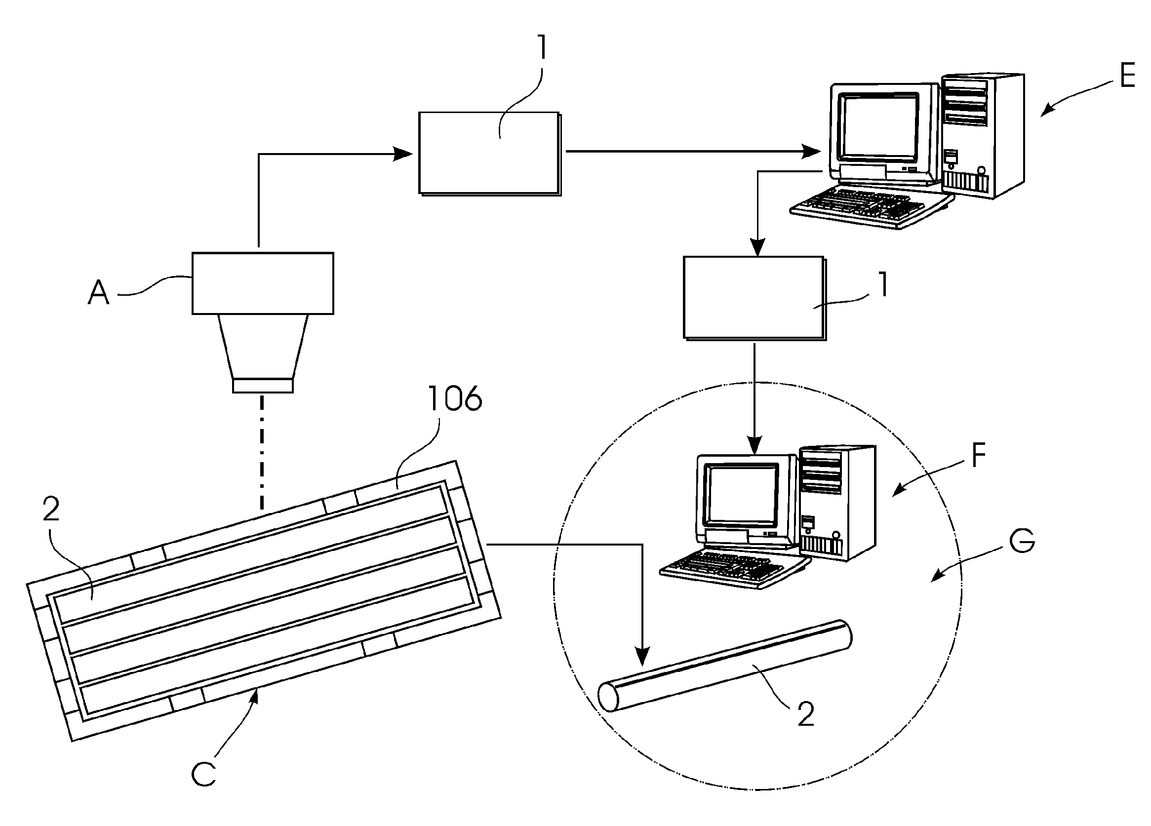
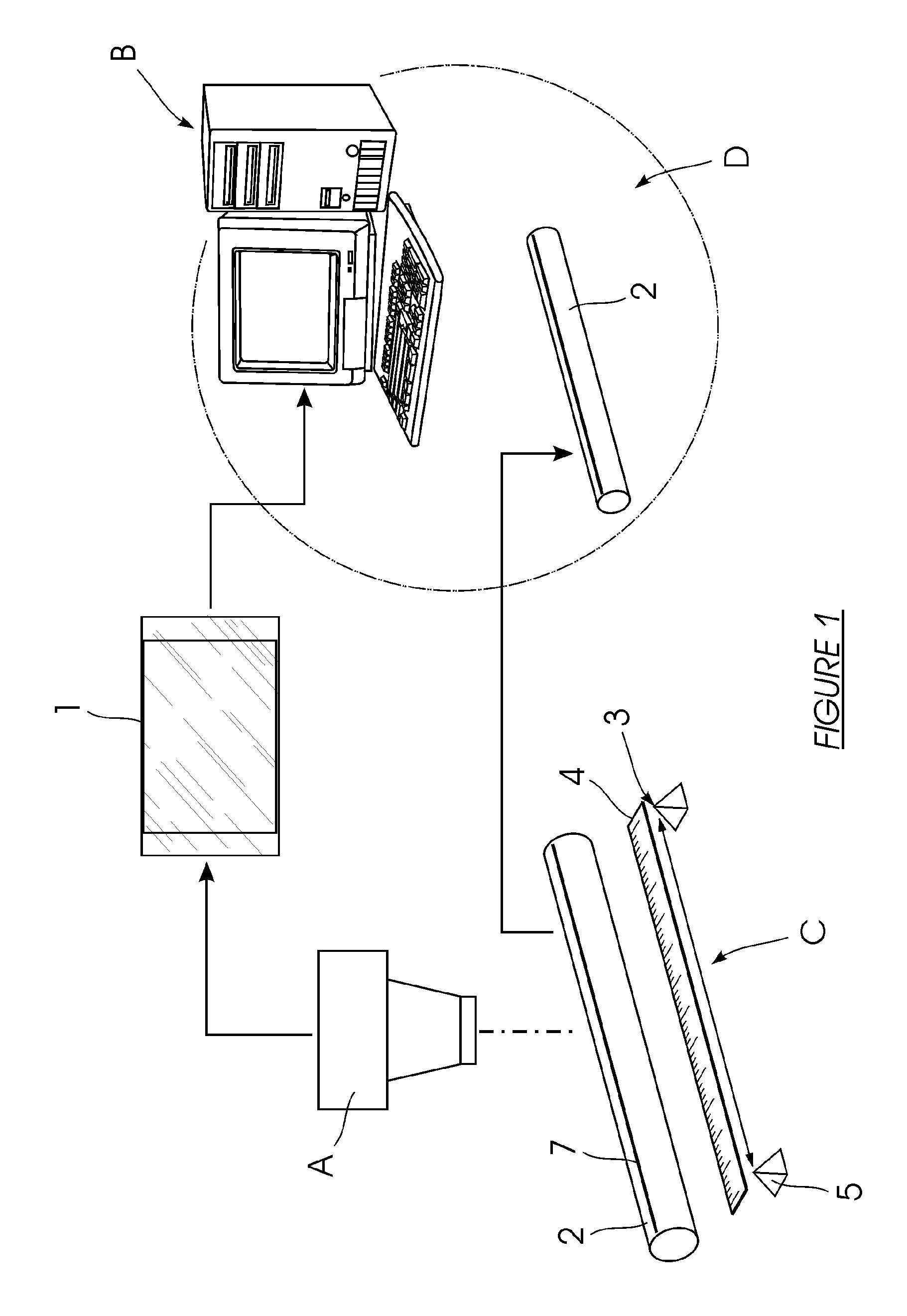
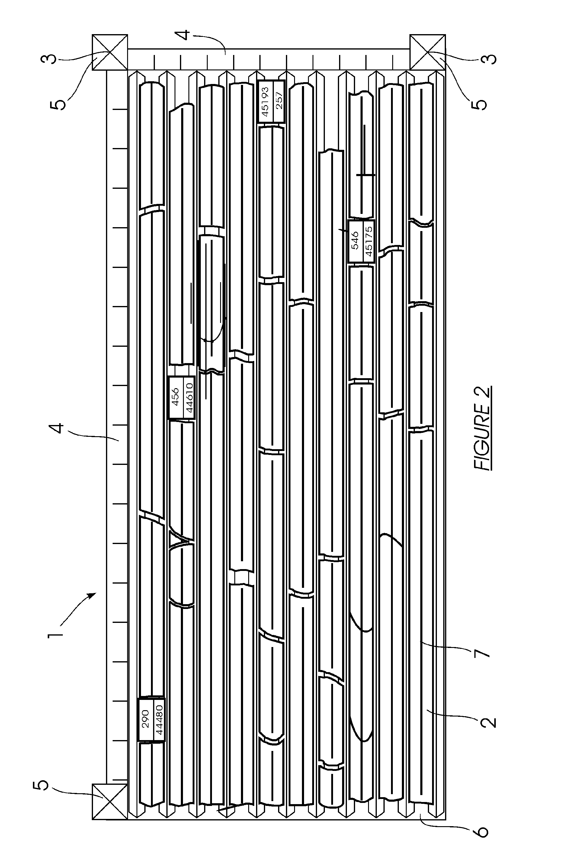
[0066]Referring to FIG. 1, the current invention involves using a digital photograph (1) of rock core (2) from a borehole for logging of structural data. The image (1) is taken using a suitable digital camera (A) and downloaded to a data processor or computer (B) for analysis using a software program which is also part of this invention. Incorporated in the image (1) is a suitable measurement and calibration scale (C) which is located next to the core (2). The measurement scale is a ruler (4), in either metric or imperial measure, for calibrating pixel size to standard measure. Shown more clearly in FIG. 2, the reference scale is represented by three pyramids (5) of known dimension and spacing. The pyramids (5) are located symmetrically at three corners of a core tray (6), with a pair of rulers (4) extending therebetween. The points (3) of the pyramids (5) are lined up with outer edges of the rulers (4).

[0067]During a drilling operation, a driller will produce a series of core runs ...


PUM


Abstract

The invention is provides a method of logging rock core. A digital photograph of core from a borehole is taken and the image is first processed. This involves calibration and correction, or un-distortion, of the digital image. A reference frame is included in the photograph to facilitate processing. The two-dimensional image is then used as a virtual three-dimensional model of the core enabling length and angle measurements to be logged. These include linear rock interval measurements as well as angular measurements of geological structures. The method is implemented using a software program which enables suitable hardware. The software program will be provided on a suitable computer readable medium. Manually logged data of the same kind is imported for comparison to data logged using the software program. All of this data can be displayed on the image and incrementally on a Stereonet as it is logged. A permanent visual record and reliable means of rapidly assessing the accuracy and quality of the data is provided. The invention also provides for automation of a significant part of the image processing and logging. The reference frame is preferably provided by a rock core tray frame having suitable indicators with known dimensions. The frame is rectangular with orthogonal lines on an upper surface. The mid-points of these lines are marked and spaced apart brackets provide for elevated lines superimposed on the orthogonal lines.

Description

FIELD OF THE INVENTION[0001]The invention relates to a method for logging data from drilled core samples of rock. The invention extends to a software program, and to a computer readable medium and a combination of hardware.BACKGROUND TO THE INVENTION[0002]The successful exploration for, delineation of, and eventual mining of ore-bodies, as well as the safe construction of massive structures such as high rise buildings and dam walls, and tunneling for civil works etc. are all dependent on a thorough knowledge of the geology of the ground. A three-dimensional (3D) understanding of the subsurface is developed from surface geological mapping, along with geophysical and geochemical surveys. However, the predictive power of such three-dimensional models is substantially limited without data from reliable and accurate measurements derived directly from the subsurface.[0003]Various drilling techniques (such as diamond drilling) are used to bore deep into the earth with the aim of producing ...

Claims


Application Information

Patent Timeline
Patent Type & Authority Applications(United States)
IPC IPC(8): G06K9/00
CPCG01N33/24
Inventor ORPEN, JOHN LISLE
Owner GROUND MODELLING TECH
Why Eureka
Try Eureka