Secure high frequency / ultra high frequency inlay, and method and apparatus for making the inlay

a high frequency/ultra high frequency inlay and high frequency technology, applied in the direction of magnets, instruments, magnets, etc., can solve the problems of security issues, yield loss along the entire production process must be accounted for and securely stored, and defeat the purpose of electronic travel documents, so as to reduce the force required for the diffusion process and improve control

Inactive Publication Date: 2008-03-27
HID GLOBAL GMBH
View PDF54 Cites 86 Cited by
  • Summary
  • Abstract
  • Description
  • Claims
  • Application Information

AI Technical Summary

Benefits of technology

[0105]The position of the insulation removal can be defined and the length of wire conductor which passes from the laser tunnel to the ultrasonic wire guide

Problems solved by technology

The fact that the personalization (individualization) of the finished product with the user credentials is performed at the end of the value chain means that security issues arise from the loss of chips, inlays and finished products before this final process.
In addition, yield loss along the entire production process must be accounted for and securely stored.
Firstly, it can be argued that the RFID chip with encryption technology could be used to store critical data relating to the production process, but this argument is only valid if the transponder functions correctly.
Secondly, the critical data could be stored at a

Method used


Image

  • Secure high frequency / ultra high frequency inlay, and method and apparatus for making the inlay
  • Secure high frequency / ultra high frequency inlay, and method and apparatus for making the inlay
  • Secure high frequency / ultra high frequency inlay, and method and apparatus for making the inlay

Examples


Embodiment Construction

[0139]Various “embodiments” of the invention will be discussed. An embodiment is an example or implementation of one or more aspects of the invention(s). Although various features of the invention may be described in the context of a single embodiment, the features may also be provided separately or in any suitable combination. Conversely, although the invention may be described herein in the context of separate embodiments for clarity, the invention may also be implemented in a single embodiment.

[0140]It should be understood that the phraseology and terminology employed herein is not to be construed as limiting, and is for descriptive purposes only.

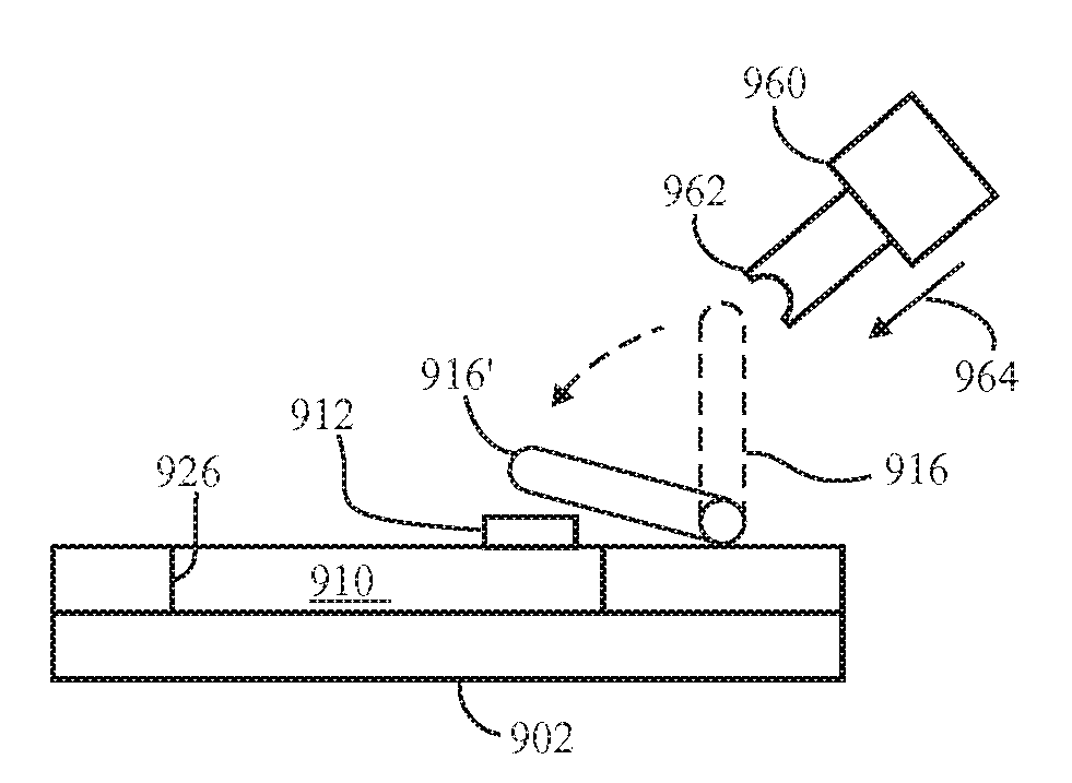
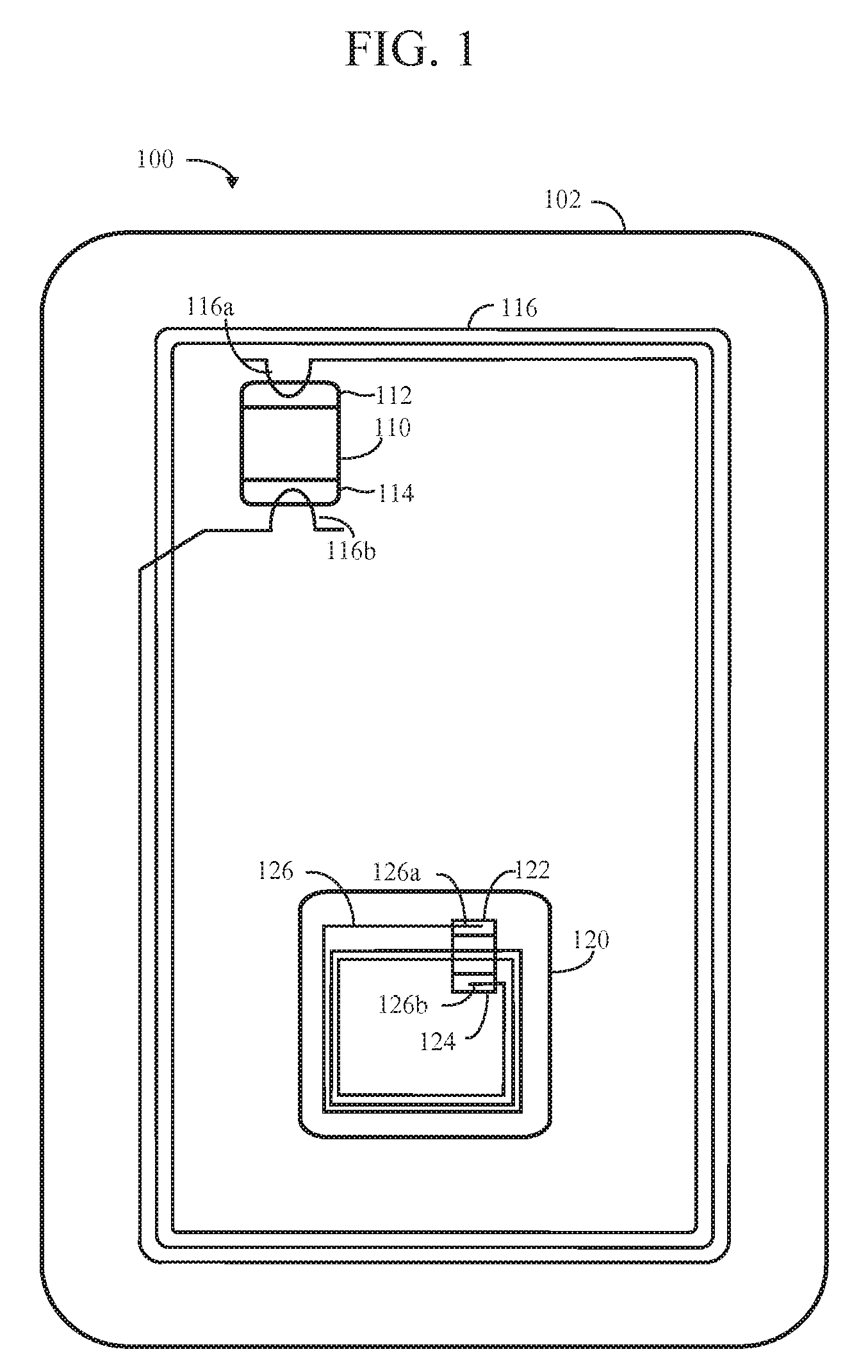
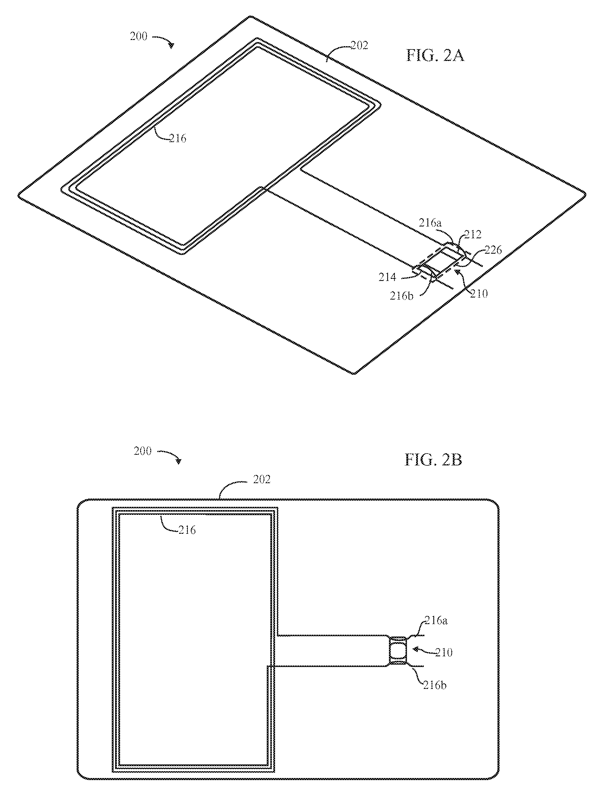
[0141]The invention relates generally to secure inlays which may be single or multi-layer substrates containing HF (high frequency) and / or UHF (ultra-high frequency) radio frequency identification (RFID, transponder) chips and, more particularly, to techniques for mounting (including embedding in or positioning on) an antenna wire to the...


PUM

PropertyMeasurementUnit
Metallic bondaaaaaaaaaa
Frequencyaaaaaaaaaa
Energyaaaaaaaaaa

Abstract

Forming an inlay comprising an antenna wire having two end portions and a site for a transponder chip, comprises: mounting the wire to a surface of substrate; and leaving the end portions of the antenna wire free-standing, as loops adjacent terminal areas of a site on the substrate for the transponder chip. With the transponder chip installed on the substrate, the free-standing loops are repositioned to be substantially directly over the terminals of the transponder chip, in preparation for interconnection of the loops to the terminals of the transponder chip, then are bonded to the terminals. An embedding tool for mounting the wire on the substrate may embed the wire in or adhesively place a self-bonding wire on a surface of the substrate. The substrate may have two transponder chips, and function as a secure inlay. An anti-skimming feature is included in the inlay.

Description

CROSS-REFERENCE TO RELATED APPLICATIONS[0001]This patent application claims benefit of the following US Provisional Patent applications, all of which are incorporated by reference in their entirety herein:[0002]60 / 826,923 filed 26 Sep. 2006 by Finn (docket # Finn-S4-PPA, hereinafter “S4”),[0003]60 / 883,064 filed 1 Jan. 2007 by Finn (docket # Finn-S5-PPA, hereinafter “S5”),[0004]60 / 884,158 filed 9 Jan. 2007 by Finn (docket # Finn-S6-PPA, hereinafter “S6”),[0005]60 / 887,294 filed 30 Jan. 2007 by Finn (docket # Finn-S7-PPA, hereinafter “S7”), and[0006]60 / 894,469 filed 13 Mar. 2007 by Finn (docket # Finn-S8-PPA, hereinafter “S8”).FIELD OF THE INVENTION[0007]In one aspect, the invention relates to mounting (either embedding in or placing on) an antenna wire on an insulating substrate, such as for (but not limited to) a secure inlay.[0008]In another aspect, the invention relates to method and apparatus for embedding an antenna wire in an insulating substrate, such as for (but not limited to...

Claims


Application Information

Patent Timeline
IPC IPC(8): H05K3/30H01P11/00H01R43/00
CPCG06K19/07327Y10T29/49124G06K19/0775G06K19/07779G06K19/07781H01L24/78H01L24/85H01L2224/78H01L2224/85H01L2924/01013H01L2924/01029H01L2924/01047H01L2924/01079H01L2924/01082H01Q1/2225H05K3/103H05K2201/10287H05K2203/0285H01L2924/00014H01L2924/01005H01L2924/01006H01L2924/01033H01L2924/01063H01L2924/01072H01L2924/01074H01L2924/01075H01L2924/014G06K19/07749Y10T29/49117Y10T29/49174Y10T29/4913Y10T29/49169Y10T29/49128Y10T29/49016Y10T29/49002Y10T29/49073H01L2924/01015H01L2224/45639H01L2224/45565H01L24/45H01L2924/10253H01L2924/3011Y10T29/49018H01L2224/45147H01L2224/45124H01L2224/45144H01L2224/48H01L2924/00H01L2224/45015H01L2224/78313H01L2224/85203H01L2224/85205H01L2924/14H01L2924/2076
Inventor FINN, DAVID
Owner HID GLOBAL GMBH
Why Eureka
Try Eureka