Manually activated roll-up window shade

a technology of window shades and activation forces, applied in the field of window shades, can solve the problems of increased costs, difficult mounting of tension cords, and increased activation force that must be applied to shade elements, and achieve the effect of low production cos

a technology of window shades and activation forces, applied in the field of window shades, can solve the problems of increased costs, difficult mounting of tension cords, and increased activation force that must be applied to shade elements, and achieve the effect of low production cos

US20080073035A1Inactive Publication Date: 2008-03-27BOS

Image

  • Manually activated roll-up window shade
  • Manually activated roll-up window shade
  • Manually activated roll-up window shade

Examples


Embodiment Construction

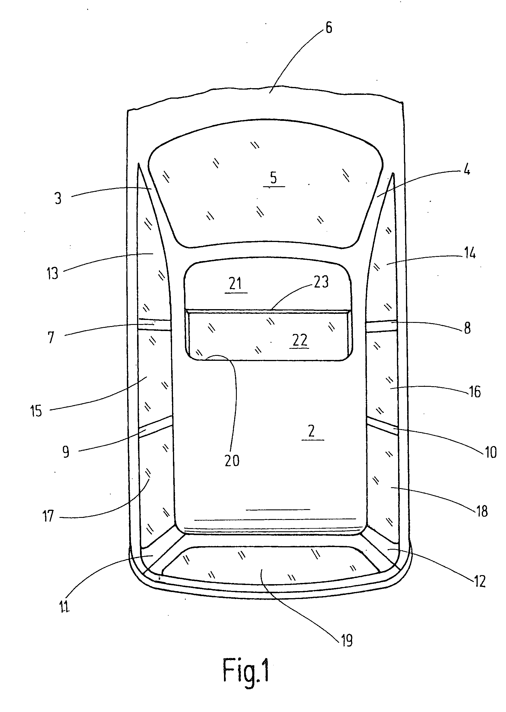
[0026] Referring to FIG. 1 of the drawings, a passenger car, in particular a station wagon 1, is shown. Two A-pillars 3 and 4 project from the front edge of the roof of the car 1. A windshield 5 is arranged between the two A-pillars 3 and 4. The windshield 5 transitions into a hood 6 at its bottom edge. Rearwards of the two A-pillars 3 are B-pillars 7 and 8, C-pillars 9 and 10, and also D-pillars 11 and 12. Front side windows 13, 14, rear side windows 15, 16, and side windows for the trunk space 17, 18 are provided between the pillars 3-12. A rear window 19 which is arranged between the two D-pillars 11, 12 is provided at the end of the car. A roof opening 20 is provided in the front area of the roof 2. A sunroof 21 that borders the front windshield 5 is arranged in the roof opening 20. The sunroof 21 can be a sliding roof or a lifting roof and can incorporate a glass roof that connects both functions to each other.

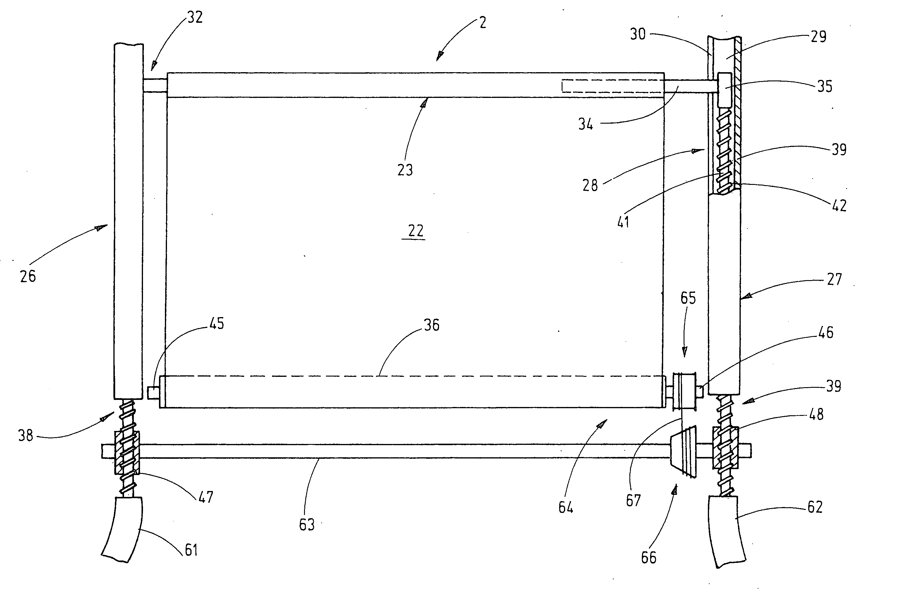
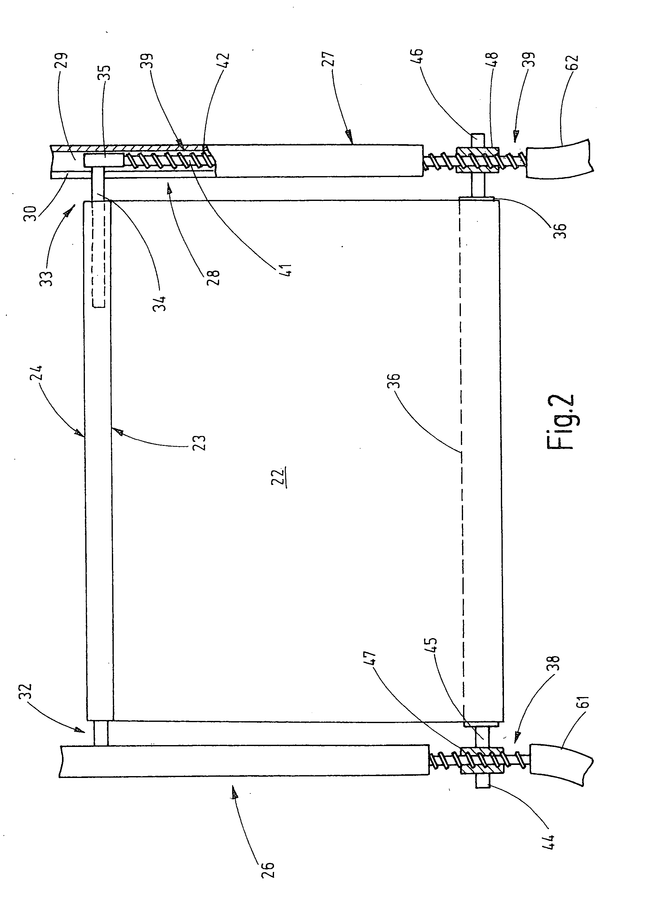
[0027] A partially extended shade element 22 is arranged underneath...


PUM


Abstract

A roll-up sunroof shade is provided that has two guide rails in addition to the tensioned shade element. A push element runs in each guide rail. Each push element is driven with a positive fit via a separate drive gear. For manual activation of the shade element, the rotational movement of the wind-up shade is transferred to the drive gears, and thus to the push elements, via a gear arrangement. In contrast, during retraction, the force acts from the push elements onto the wind-up shaft via the drive gears in order to generate the necessary rotational movement of the wind-up shaft.

Description

FIELD OF THE INVENTION [0001] The present invention relates to window shades for motor vehicles. BACKGROUND OF THE INVENTION [0002] As a rule, manually actuated roll-up window shades are somewhat simpler in construction than electrically operated roll-up window shades. For example, electrically operated roll-up window shades require a drive motor, which increases costs. If a roll-up window shade is located in the effective arms reach of the driver, a manually activated roll-up window shade can be used easily. A preferred type of roll-up window shades that can be actuated manually is a roll-up sunroof shade. Roll-up sunroof shades are generally designed such that they can remain in any arbitrary intermediate position. [0003] The use of a wind-up shaft that is biased in a wind-up direction of the shade element with the help of a spring motor is the simplest form of such a roll-up shade. The edge of the shade element away from the wind-up shaft is connected to a pull rod that is guided...

Claims


Application Information

Patent Timeline
27 Mar 2008
Publication
US20080073035A1
IPC
E06B9/08
CPC
B60R5/047; B60J1/2058; B60J1/20; B60J3/00; B60J3/02
Inventors
SCHLECHT, WERNER