
Optical system

a technology of optical system and optical axis, applied in the field of optical system, can solve the problems of large motor and elevated power requirements, significant handicaps, unreliability and even failure, etc., and achieve the effect of not sacrificing angular sensitivity or precision

Inactive Publication Date: 2008-03-27
KANE DAVID M
View PDF3 Cites 10 Cited by
  • Summary
  • Abstract
  • Description
  • Claims
  • Application Information

AI Technical Summary

Benefits of technology

This approach allows for a significant increase in optical leverage, enabling larger beam excursions with smaller, lighter components, resulting in improved angular resolution and response speed, and enables the system to accurately determine radiation characteristics and track sources with high precision.

Problems solved by technology

Both approaches entail relatively high moments of inertia, and accordingly large motors and elevated power requirements.
Such configurations require extremely adverse tradeoffs and compromises between, on one hand, undesirably high cost and size, and on the other hand structural weaknesses that lead to unreliability and even failure.
These are significant handicaps for—in particular—devices that may be for use in airplanes and satellites.
Even in these cases, such drawbacks might be acceptable if such systems provided superb performance, but unfortunately angular resolution in conventional systems of various types is generally no better than two-thirds of a degree—sometimes as coarse as ten degrees and more.
The poor angular resolution and other performance limitations of such sensors arise in part from use of fixed, very large sensor assemblies, typically quad cells, CCD or CMOS arrays, at a focal plane—with fixed fields of view.
These components accordingly also suffer from limited fields of regard.
Furthermore the necessity for downloading into a computer memory the massive volumes of data from multimegabyte sensor arrays makes the frame rate of these systems extremely slow.
This strategy, however, is counterproductive in that it only compounds the data-download problem, while also yielding intrinsically coarse angular resolution and very nonlinear angular mapping.
In other words these systems are squeezed between the need for high resolution and the need for broad field of regard; this squeeze comes down to an all-but-prohibitive demand for dynamic range, or bandwidth.
Data congestion, furthermore, is doubly problematic because in these systems the entire contents of every frame must be retrieved before that frame can be searched for an optical source of interest.
One rather unnoticed contributor to inadequate dynamic range is the direct relationship between gimbal angle or scan-mirror angle and excursion of the beam in the external scanned volume.
Since the direct effect of mechanical rotation is relatively slow for gimbals, and relatively limited in overall angular excursion for scan mirrors, the external beam-angle excursion is either slow or limited, or both.
Unfortunately these reported distances and therefore the angular mapping of a PSD are nonlinear, to the extent of several percent at the PSD edges—aggravating the analogous handicap introduced by a fish-eye or other wide-angle lens—and are also temperature sensitive.
The detector may report accurately that an optical source has been sensed, but fail to report accurately where that object is, unless it is near the nominal center, or origin of coordinates.
In any conventional detector, however, this solution is impractical due to the lumbering response of an associated gimbal system, or even of a scan mirror that is redirecting the light into the detector aperture.
In another sense, however, this is a difficult case from the standpoint of confusion, because the object may have been designed to look (for its guidance) backward at the source rather than forward at the vehicle—in which event the ejection of reflecting particles cannot confuse the directional-control mechanisms of the object, as long as the pointing entity can keep the vehicle in view.
Such mirrors are too bulky and heavy to overcome the previously discussed problems of response speed.
Hence the overall device and even the individual mirrors are too big and heavy to free the optical-detection art from the response-speed and related limitations discussed above.
These mirror wheels are ordinarily made to spin continuously; hence the individual mirrors of such an array lack independent maneuverability for customized control movements.
Accordingly they are poorly suited for practical use in rapid detection and tracking of a particular source object.
For present purposes, however, any interest in such devices is academic, as the movable components are relatively huge and far too massive to be useful in any rapid-response system.
As can now be seen, the related art fails to resolve the previously described problems.

Method used


Image

  • Optical system
  • Optical system
  • Optical system

Examples


Embodiment Construction

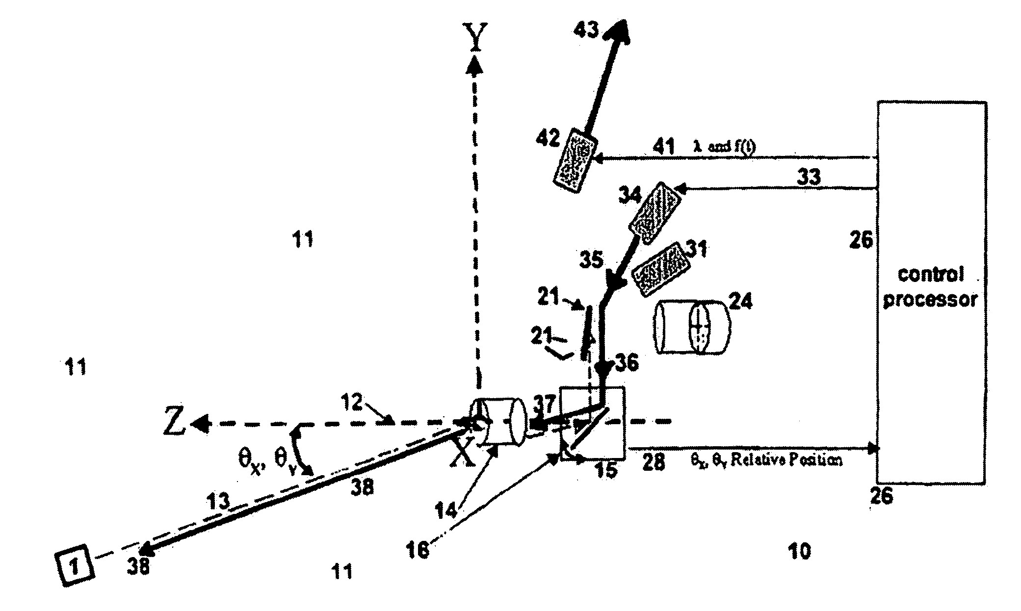
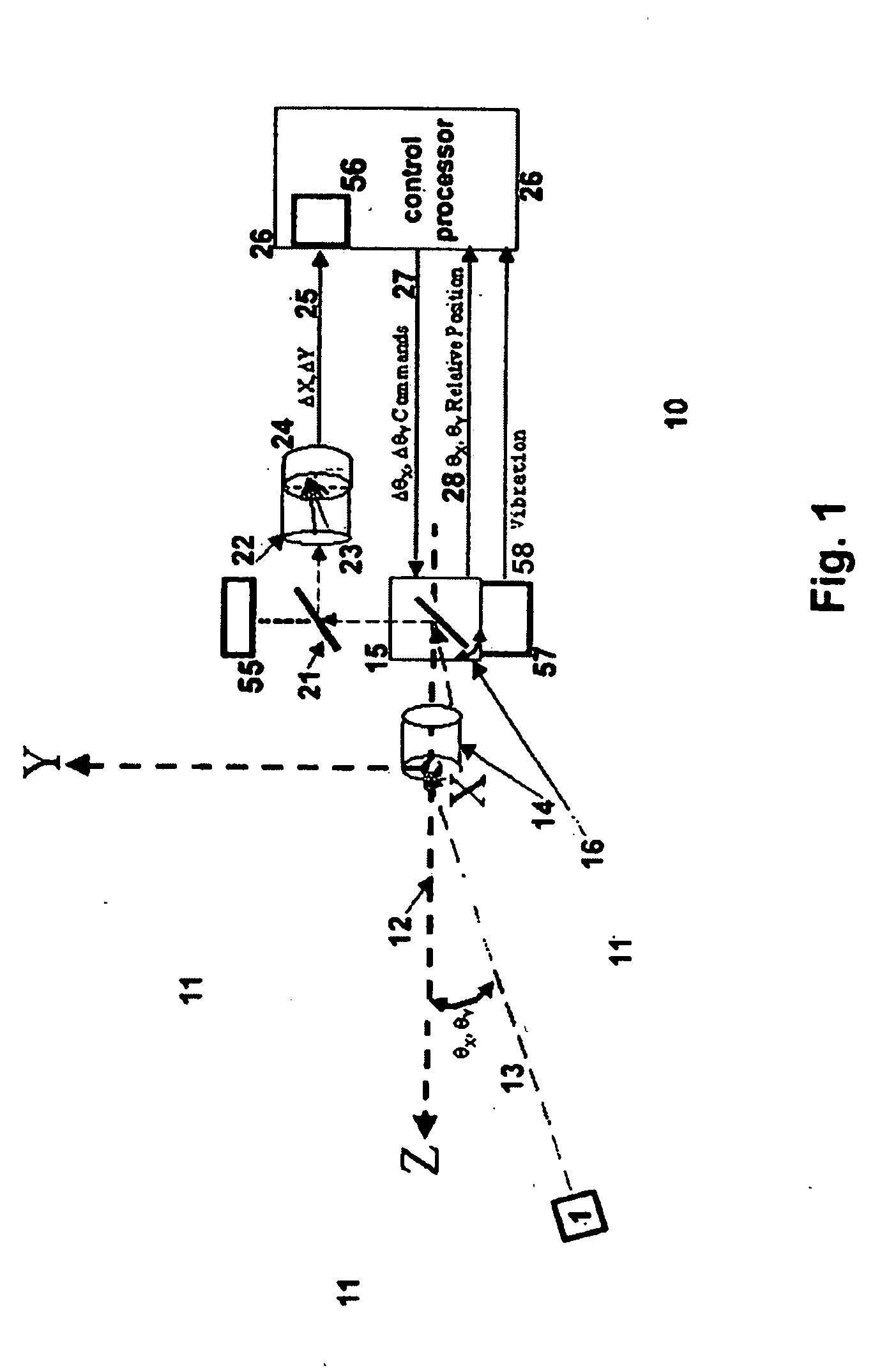
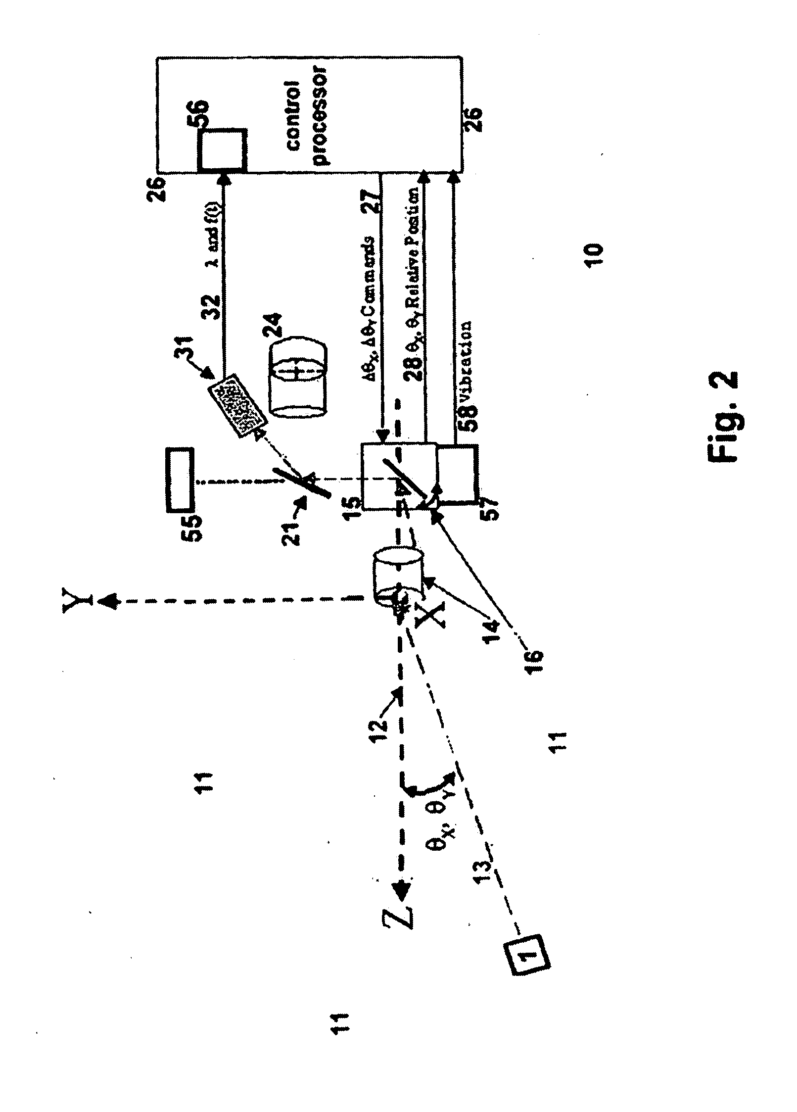
[0117] In preferred embodiments, the invention provides a low-cost sensor system 10 (FIG. 1) capable of detecting and locating active illumination sources—or objects illuminated by such sources. In some preferred embodiments (FIGS. 2 through 4), the sensor system of the invention can also respond to the detected light source by returning a light beam 38 (FIG. 3) or an object, and in some cases by initiating a distance-determining or other investigation (Function 4, FIG. 4) of the source or objects associated with the source.

[0118] In particularly preferred embodiments, initial detection of a radiation source or illuminated object is qualified by filters that implement expectations as to the characteristics of such sources or objects that are of interest. For instance, when anticipated sources are infrared, or are in other particular spectral regions, spectral filters are placed at convenient positions in the optical path—usually but not necessarily associated with the fold mirror 2...


PUM


Abstract

In preferred forms of the invention an array of MEMS mirrors or small mirrors inside an optical system operates closed-loop. These mirrors direct external source light, or internally generated light, onto an object—and detect light reflected from it onto a detector that senses the source. Local sensors measure mirror angles relative to the system. Sensor and detector outputs yield source location relative to the system. One preferred mode drives the MEMS mirrors, and field of view seen by the detector, in a raster, collecting a 2-D or 3-D image of the scanned region. Energy reaching the detector can be utilized to analyze object characteristics, or with an optional active distance-detecting module create 2- or 3-D images, based on the object's reflection of light back to the system. In some applications, a response can be generated. The invention can detect sources and locations for various applications.

Description

[0001] Wholly incorporated by reference herein is coowned U.S. provisional patent application Ser. 60 / 433,301, whose priority benefit is hereby asserted. RELATED DOCUMENTS [0002] Closely related documents are other, coowned U.S. utility-patent documents and references—also incorporated by reference. Those documents are in the names of: [0003] Kane, provisional application Ser. 60 / 381,286, also incorporated by reference in the provisional application that is mentioned above; [0004] Kane et al., application Ser. No. 10 / 142,654 “HIGH-SPEED, LOW-POWER OPTICAL MODULATION APPARATUS AND METHOD”. FIELD OF THE INVENTION [0005] This invention relates generally to systems and methods for automatically detecting light from an object, determining direction or other characteristics (such as distance, spectral properties, or an image) of the detected light or the object, and possibly responding to the detected light. BACKGROUND [0006] Some conventional systems and methods for accomplishing these g...

Claims


Application Information

Patent Timeline
Patent Type & Authority Applications(United States)
IPC IPC(8): G01J1/20
CPCG01J3/021G01J3/0256G01J3/0289G02B26/105G01S17/89G02B26/0833G01S17/023G01S17/86
Inventor KANE, DAVID M.
Owner KANE DAVID M
Learn More