
Data communication method and apparauts using power line

a technology of power line and data communication, applied in the direction of power distribution line transmission, digital transmission, transmission, etc., can solve the problems of complicated installation increased manufacturing cost of the plc system, and signal interference with the adjacent device, so as to simplify the configuration

Inactive Publication Date: 2008-03-27
AVERD
View PDF0 Cites 8 Cited by
  • Summary
  • Abstract
  • Description
  • Claims
  • Application Information

AI Technical Summary

Benefits of technology

[0006]Accordingly, the present invention has been made in view of the above-mentioned problems occurring in the prior art, and it is a primary object of the present invention to provide a data communication method and apparatus using a power line, which transmits and receives data of several kbps between a transmitter and a receiver connected in a closed circuit by cutting an AC voltage waveform into the form of a square-wave pulse signal and loading the data on the AC voltage signal to thereby prevent the data-loaded voltage signal from unnecessarily propagating to neighboring devices, require no filter, and simplify configurations of the transmitter and the receiver to transmit the data at a low cost.

Problems solved by technology

However, since the PLC method carries a signal on an open power line to transmit the signal, the signal may interfere with a device adjacent to a device to which the signal is transmitted.
Accordingly, the manufacturing cost of a PLC system is greatly increased and installation of the PLC system is made complicated.

Method used


Image

  • Data communication method and apparauts using power line
  • Data communication method and apparauts using power line
  • Data communication method and apparauts using power line

Examples


Embodiment Construction

[0019]The present invention will be described in detail with reference to the appended drawings.

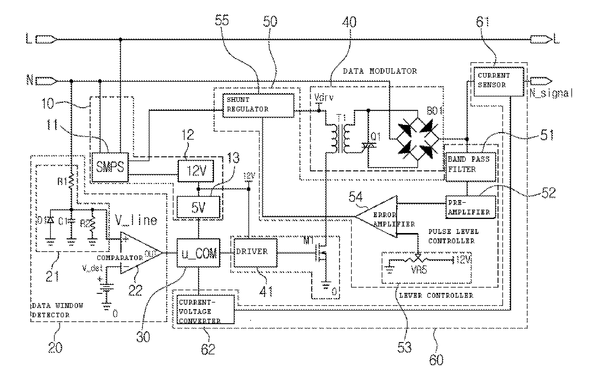
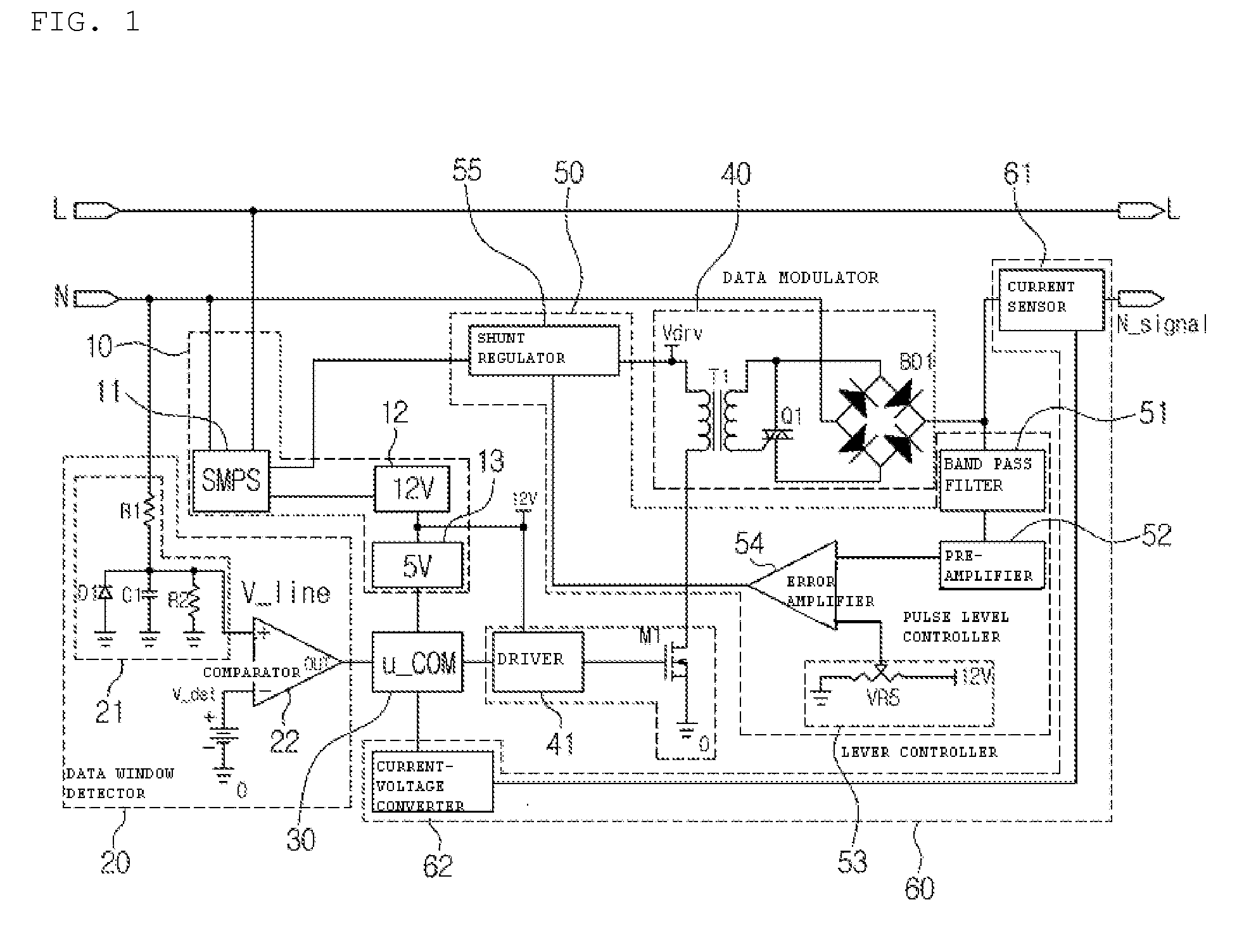
[0020]FIG. 1 illustrates a configuration of a transmitter of a data communication apparatus using a power line according to an embodiment of the present invention. Referring to FIG. 1, the transmitter includes a transmitter power supply unit 10 for receiving power from a power line N and generating a DC voltage for operating components of the transmitter, a data window detector 20 for clamping an AC voltage from the power line N and comparing the clamped voltage with a reference voltage to detect a section of the waveform of the AC voltage, on which data will be loaded, a microcomputer 30 for transmitting the data in a positive voltage period based on the signal output from the data window detector 20 and controlling data transmission in response to a reception feedback signal from a receiver, a data modulator 40 for loading the data transmitted from the microcomputer 30 on the AC voltage...


PUM


Abstract

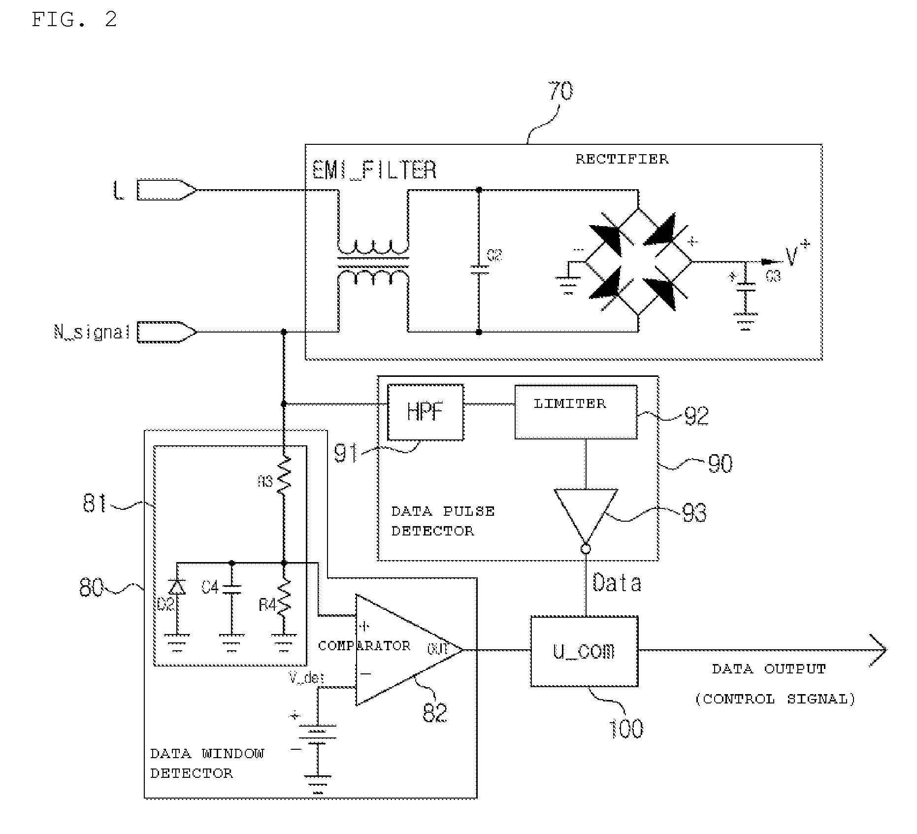
Disclosed herein is a data communication method and apparatus for transmitting and receiving data in the form of a square-wave signal having a specific amplitude using an AC power line between a transmitter and a receiver connected in a closed circuit by cutting an AC voltage waveform and loading the data on the AC voltage waveform. The transmitter comprises a transmitter power supply unit 10, a data window detector 20 for clamping a voltage signal from the power line N to detect a section of the voltage signal on which data will be loaded, a microcomputer 30 for transmitting the data in a data-loading period and controlling data transmission in response to a reception feedback signal from a receiver, a data modulator 40 for loading the data transmitted from the microcomputer 30 on the voltage signal from the power line N in the form of a pulse signal, a pulse level controller 50 for adjusting a drive voltage of the data modulator 40 to control a data transmission pulse level to be stabilized, and a reception detector 60 for feeding back information on whether the receiver receives the signal transmitted from the transmitter to the microcomputer 30. The receiver comprises a data window detector 80, a data pulse detector 90 and a microcomputer 100. Logic circuits can replace the microcomputer 100.

Description

BACKGROUND OF THE INVENTION[0001]1. Field of the Invention[0002]The present invention relates to communication using an AC power line, and more particularly, to a data communication method and apparatus for transmitting and receiving data in the form of a square-wave signal having a specific amplitude using an AC power line between a transmitter and a receiver connected in a closed circuit by cutting an AC voltage waveform and loading the data on the AC voltage waveform.[0003]2. Background of the Related Art[0004]Generally, a data communication method using a power line network becomes the center of attention because it uses the existing power lines without installing an additional communication line, and associated equipment for carrying out the data communication method is being developed.[0005]A power line communication (PLC) method that has been spotlighted recently has a merit of being capable of transmit large-capacity data at high speed because it uses a high frequency. Howev...

Claims


Application Information

Patent Timeline
IPC IPC(8): H04B3/54
CPCH04B2203/5412H04B3/54
Inventor NOH, SI YOUL
Owner AVERD
Learn More