Shaft bearing seal

a technology for shaft bearings and seals, which is applied to bearing components, ball bearings, engine seals, etc., can solve the problems of lubricant reaching and seals that are not suitable for hand-held power tools

Inactive Publication Date: 2008-03-27
HILTI AG
View PDF14 Cites 5 Cited by
  • Summary
  • Abstract
  • Description
  • Claims
  • Application Information

AI Technical Summary

Benefits of technology

[0010] This and other objects of the present invention, which will become apparent hereinafter, are achieved according to the present invention by providing a shaft bearing seal of the type discussed above and in which the sealing ring has aeration recesses which connect the annular gap with the lubricant containing chamber. The aeration recesses permit to remove the lubricant, which penetrated in the annular gap during the operation or shut-down of the power tool as a result of a vertical orientation of the bearing, from the annular gap. To this end, a dynamic effect is used which is produced by a rotation of the sealing ring that limits the annular gap on one side, relative to another limitation that limits the annular gap on the second side. The sealing ring can be fixedly connected, e.g., with the shaft for joint rotation therewith, and the limiting element can be fixedly secured to the housing element or vice versa. The aeration recesses aerate the annular gap. The aeration of the annular gap during operation prevents development of underpressure in the annular gap that can cause an aspiration of lubricant in the annular gap or its retention there.

Problems solved by technology

The drawback of the known shaft bearing seals consists in that despite the labyrinth-shaped annular gap, in particular at a vertical orientation of the shaft, the lubricant reaches the bearing and can leave the lubricant-receiving chamber through the bearing.
Such seals are not suitable for hand-held power tools which, e.g., are often used in overhead works and have the shaft oriented vertically for an extended time period in an operational or shut-down condition of the power tool when no lubricant should flow through the shaft bearing.

Method used


Image

  • Shaft bearing seal
  • Shaft bearing seal
  • Shaft bearing seal

Examples


Embodiment Construction

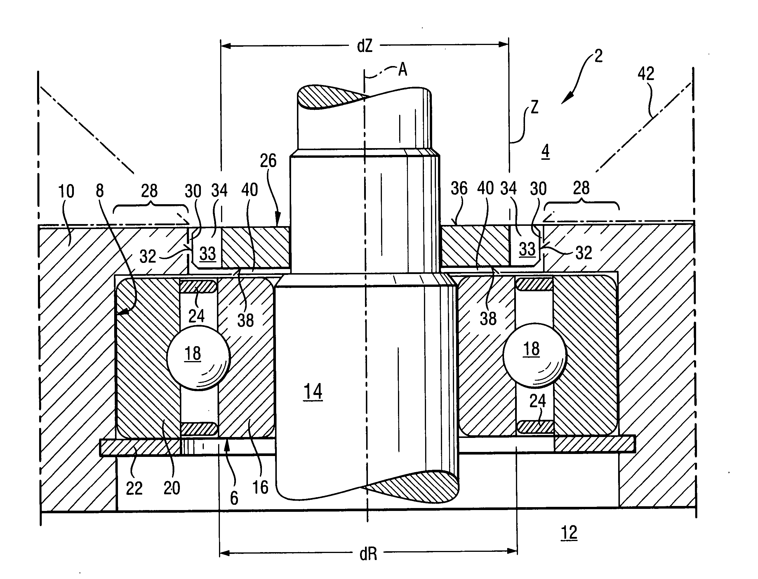
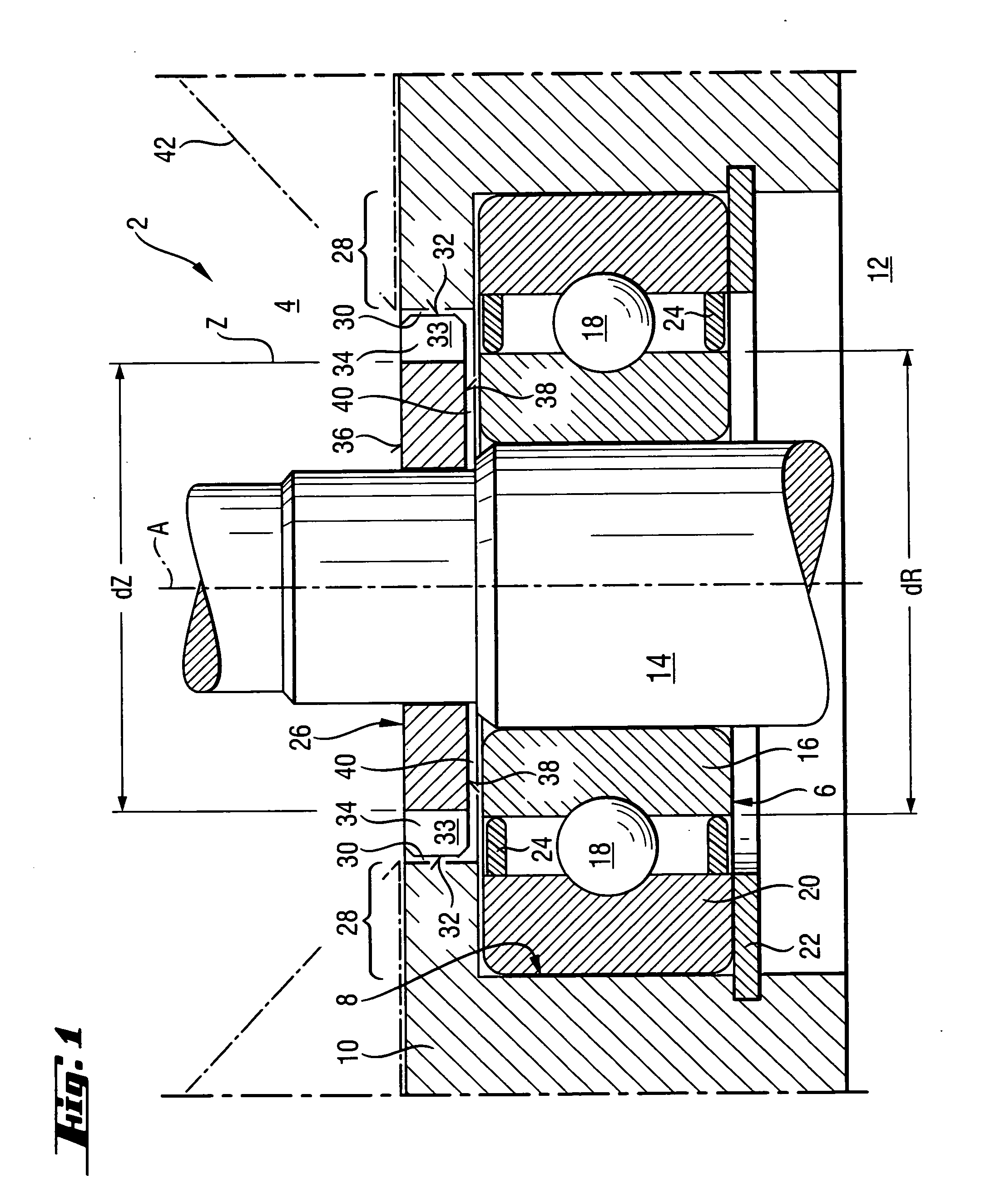
[0030]FIG. 1 shows a shaft bearing seal 2 which is provided on a grease-containing chamber 4 of a gear housing, not shown in detail, of a hand-held power tool, e.g., in form of a hammer drill or a screw driving tool. The shaft bearing seal 2 is provided on a bearing 6 that is retained in the housing opening 8 of a wall-shaped housing element 10. The housing element 10 separates the grease-containing chamber 4 from an outer chamber 12 of a motor housing, not shown in detail.

[0031] The bearing 6 serves for supporting a shaft 14 for rotation about an axis A. The shaft 14 projects from the outer chamber 12 into the grease-receiving chamber 4. The bearing 6 has an inner ring 16 which, e.g., is press fit-mounted on the shaft 14 for joint rotation therewith. The inner ring 16 is rotated relative an outer ring 20 of the bearing 6 by a ball-shaped bearing body 18. The outer-ring 20 is held fixedly in the housing element 10 and is axially secured with a circlip 22. Between the inner ring 16 ...


PUM


Abstract

A seal (2) for a bearing (6) that rotatably supports a shaft (14) extending through a housing opening (8) of a housing element (10) that limits, at least partially, a lubricant-receiving chamber (4), includes a sealing ring (26) retainable between the housing element (10) and the shaft (14) and forming together with a limiting element (28) an annular gap (30), and having aeration recesses (34) which connect the annular gap (30) with the grease-containing chamber (4).

Description

BACKGROUND OF THE INVENTION [0001] 1. Field of the Invention [0002] The present invention relates to a seal for a bearing that rotatably supports a shaft. The shaft extends through a housing opening of a housing element that limits, at least partially, a chamber containing a lubricant in form of a lubricating grease or oil. Between the lubricant-containing chamber and the bearing, there is provided a sealing ring that surrounds the shaft and is retained between the shaft and the housing element for protecting the bearing from the lubricant. The sealing ring forms, together with a limiting element, an annular gap. [0003] 2. Description of the Prior Art [0004] The seals of the type descried above, are provided, e.g., on lubricant-receiving chambers or receptacles for gear units of, e.g., hand-held power tools. The sealing ring prevents the lubricant, which is provided in the associated gear housing, from directly contacting the bearing and from flowing through the bearing from the gea...

Claims


Application Information

Patent Timeline
Patent Type & Authority Applications(United States)
IPC IPC(8): F16C33/76
CPCB25F5/02F16C33/805F16C33/7896F16J15/164F16C19/06
Inventor DORNER, STEFANHARTMANN, MARKUSREHM, HERBERT
Owner HILTI AG
Why Eureka
Try Eureka