
Method for adaptive prediction of stack voltage in automotive fuel cell systems

a fuel cell and stack voltage technology, applied in the field of stack voltage adaptive prediction, can solve the problems of low dynamic power of a fuel cell system, relatively high manufacturing cost, and time delay from system start-up to driveability, and may not be acceptabl

Inactive Publication Date: 2008-03-27
GM GLOBAL TECH OPERATIONS LLC
View PDF3 Cites 21 Cited by
  • Summary
  • Abstract
  • Description
  • Claims
  • Application Information

AI Technical Summary

Benefits of technology

[0017]In accordance with the teachings of the present invention, a method for revising the current / voltage relationship of a fuel cell stack over time is disclosed. The method includes defining a reference polarization curve of the stack when it is new that identifies the relationship between the voltage and the current of the stack. As the stack ages, the polarization curve is revised based on the changing relationship between the stack voltage and current. When the stack is operating at low load and current density where kinetic voltage losses of the stack dominate, a first adaptation value is revised as the difference between the actual stack voltage and the stack voltage of the reference polarization curve.

Problems solved by technology

MEAs are relatively expensive to manufacture and require certain conditions for effective operation.
The dynamic power of a fuel cell system is limited.
Further, the time delay from system start-up to driveability and low acceleration of the vehicle may not be acceptable.
The voltage cycles can decrease the stack durability.
However, vehicle acceleration may require 100 kW or more of power.
This may result in limiting the stack current to 400A.
Various designs have been proposed in the art to eliminate the DC / DC converter because it is large, costly and heavy.
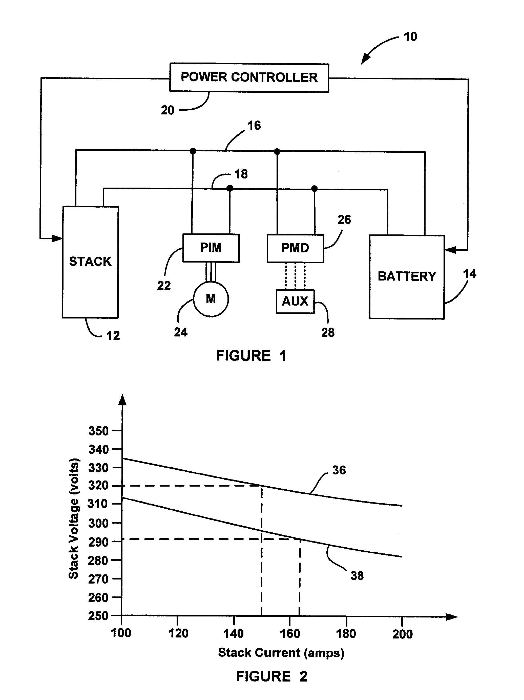
However, for the old stack, which is only able to generate about 290 volts, the compressor speed and the hydrogen flow would need to be set for about 163 amps of stack current to meet the 48 kW of requested power.

Method used


Image

  • Method for adaptive prediction of stack voltage in automotive fuel cell systems
  • Method for adaptive prediction of stack voltage in automotive fuel cell systems
  • Method for adaptive prediction of stack voltage in automotive fuel cell systems

Examples


Embodiment Construction

[0023]The following discussion of the embodiments of the invention directed to a method for determining the current / voltage relationship of a fuel cell stack by revising a reference polarization curve as the stack ages is merely exemplary in nature, and is in no way intended to limit the invention or its applications or uses. For example, the power management algorithm of the invention discussed below has particular application for fuel cell system including a fuel cell stack and a rechargeable energy storage system. However, the power management algorithm can also be used to revise a stack polarization curve for a stack in a system that does not include a battery.

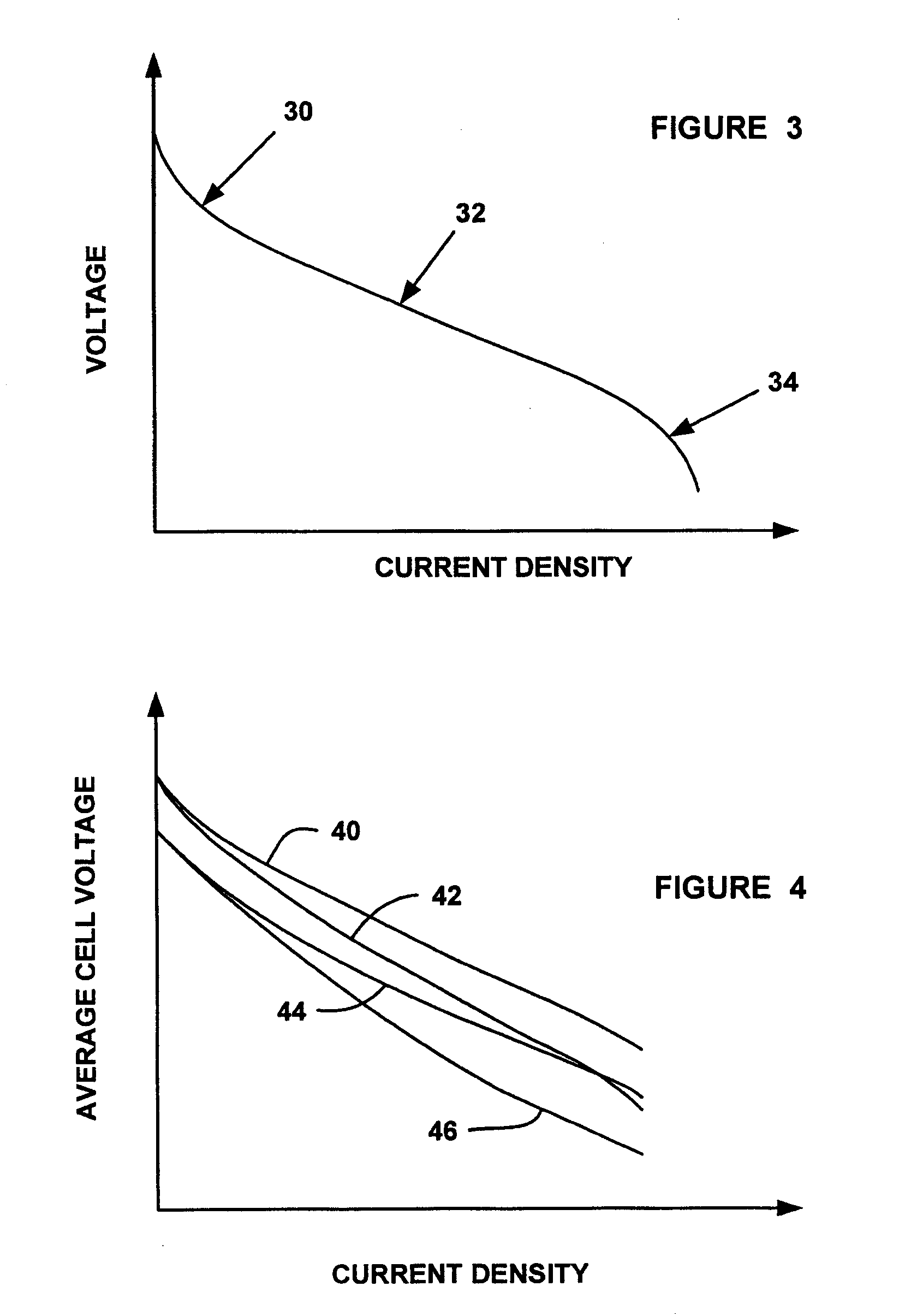
[0024]The qualitative behavior of the voltage / current relationship of a fuel cell stack is well known from electrochemistry. FIG. 3 is a graph with cell current density on the horizontal axis and average cell voltage on the vertical axis showing a typical polarization curve or voltage / current relationship for a fuel cell s...


PUM

PropertyMeasurementUnit
poweraaaaaaaaaa
currentaaaaaaaaaa
stack currentaaaaaaaaaa

Abstract

A method for revising a reference polarization curve of a fuel cell stack that identifies the relationship between the voltage and the current of the stack over time. When the stack is operating at a low load where kinetic voltage losses of the stack dominate, a first adaptation value is revised as the difference between the actual stack voltage and the stack voltage of the reference polarization curve. When the stack is operating at higher loads where ohmic voltage losses of the stack dominate, a second adaptation value is revised as the difference between the actual stack voltage and the stack voltage of the reference polarization curve.

Description

BACKGROUND OF THE INVENTION[0001]1. Field of the Invention[0002]This invention relates generally to a method for revising the current / voltage relationship of a fuel cell stack over time and, more particularly, to a method for revising the current / voltage relationship of a fuel cell stack as it ages that includes changing a first adaptation value when the stack is operating in a kinetic region and changing a second adaptation value when the stack is operating in an ohmic region.[0003]2. Discussion of the Related Art[0004]Hydrogen is a very attractive fuel because it is clean and can be used to efficiently produce electricity in a fuel cell. A hydrogen fuel cell is an electrochemical device that includes an anode and a cathode with an electrolyte therebetween. The anode receives hydrogen gas and the cathode receives oxygen or air. The hydrogen gas is dissociated in the anode to generate free hydrogen protons and electrons. The hydrogen protons pass through the electrolyte to the catho...

Claims


Application Information

Patent Timeline
Patent Type & Authority Applications(United States)
IPC IPC(8): H01M2/00
CPCH01M8/04552H01M8/04559H01M8/04649Y02T90/32H01M2008/1095H01M2250/20Y02E60/50H01M8/04992Y02T90/40
Inventor LIENKAMP, SEBASTIANKRAUSE, BERND
Owner GM GLOBAL TECH OPERATIONS LLC
Learn More