
Image Development Apparatus and Image Forming Apparatus Using the Same, and Image Development Method and Image Forming Method Using the Same

Inactive Publication Date: 2008-03-27
SEIKO EPSON CORP
View PDF2 Cites 12 Cited by
  • Summary
  • Abstract
  • Description
  • Claims
  • Application Information

AI Technical Summary

Benefits of technology

[0010]An advantage of some aspects of the invention is to provide an image development apparatus that swiftly detects any change occurred to the characteristics of a developer, an image forming apparatus using the image development apparatus, and an image development method, and an image forming method using the image development method.
[0011]An image development apparatus of the invention includes: a developer carrier that carries thereon a liquid developer being a carrier solution including dispersed toner particles each made of a coloring agent and a resin; a developer supply member that supplies the developer to the developer carrier; a developer compression member that is opposing the developer carrier, and compresses any solid content of the developer to the side of the developer carrier through application of an electric field to the developer on the developer carrier supplied by the developer supply member; a developer compression member voltage application unit that applies a voltage to the developer compression member; and a current detection unit that detects a current flowing from the developer compression member to the developer carrier. This configuration successfully enables detection of any change occurring to the characteristics of a developer based on fluctuations of a current, thereby enabling to quickly dealing with any problems if occurred.
[0012]The current detection unit performs averaging of a current value, for use as a detection value, being a result of performing current detection for a predetermined length of time. As such, the detection can be performed with good accuracy.

Problems solved by technology

As a result, the toner particles are pushed against one another, and this deteriorates the dispersion among the toner particles.
As a result, the developer may suffer from some changes of ratio between the toner particles and the carrier solution.
This resultantly causes problems of causing a change of image density, image disturbance in streaks called ribs, fogging over a non-image portion, and others.

Method used


Image

  • Image Development Apparatus and Image Forming Apparatus Using the Same, and Image Development Method and Image Forming Method Using the Same
  • Image Development Apparatus and Image Forming Apparatus Using the Same, and Image Development Method and Image Forming Method Using the Same
  • Image Development Apparatus and Image Forming Apparatus Using the Same, and Image Development Method and Image Forming Method Using the Same

Examples


Embodiment Construction

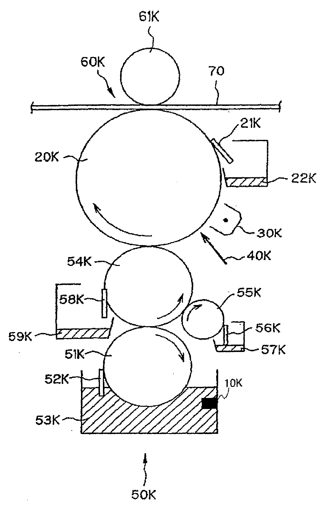
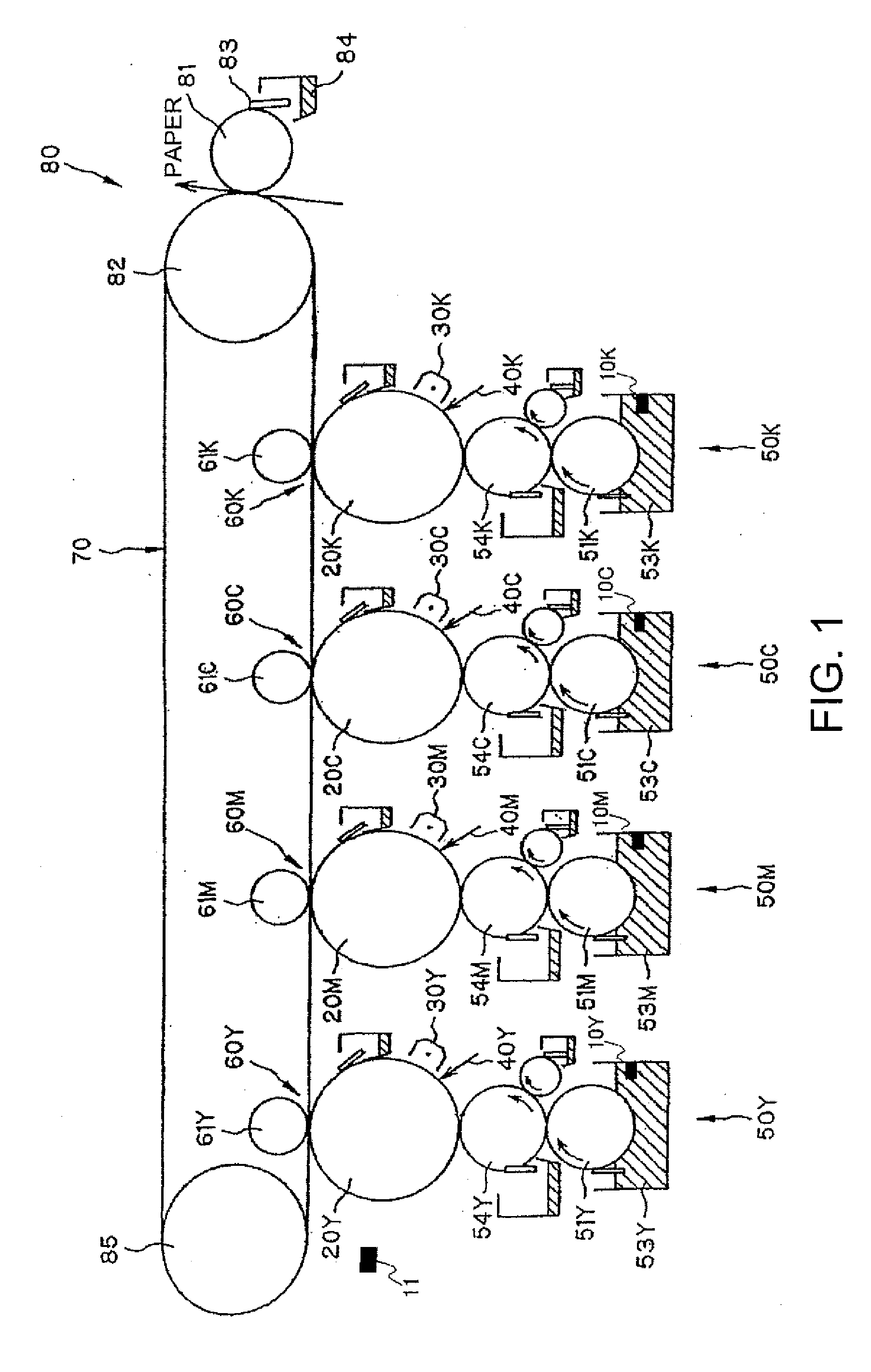
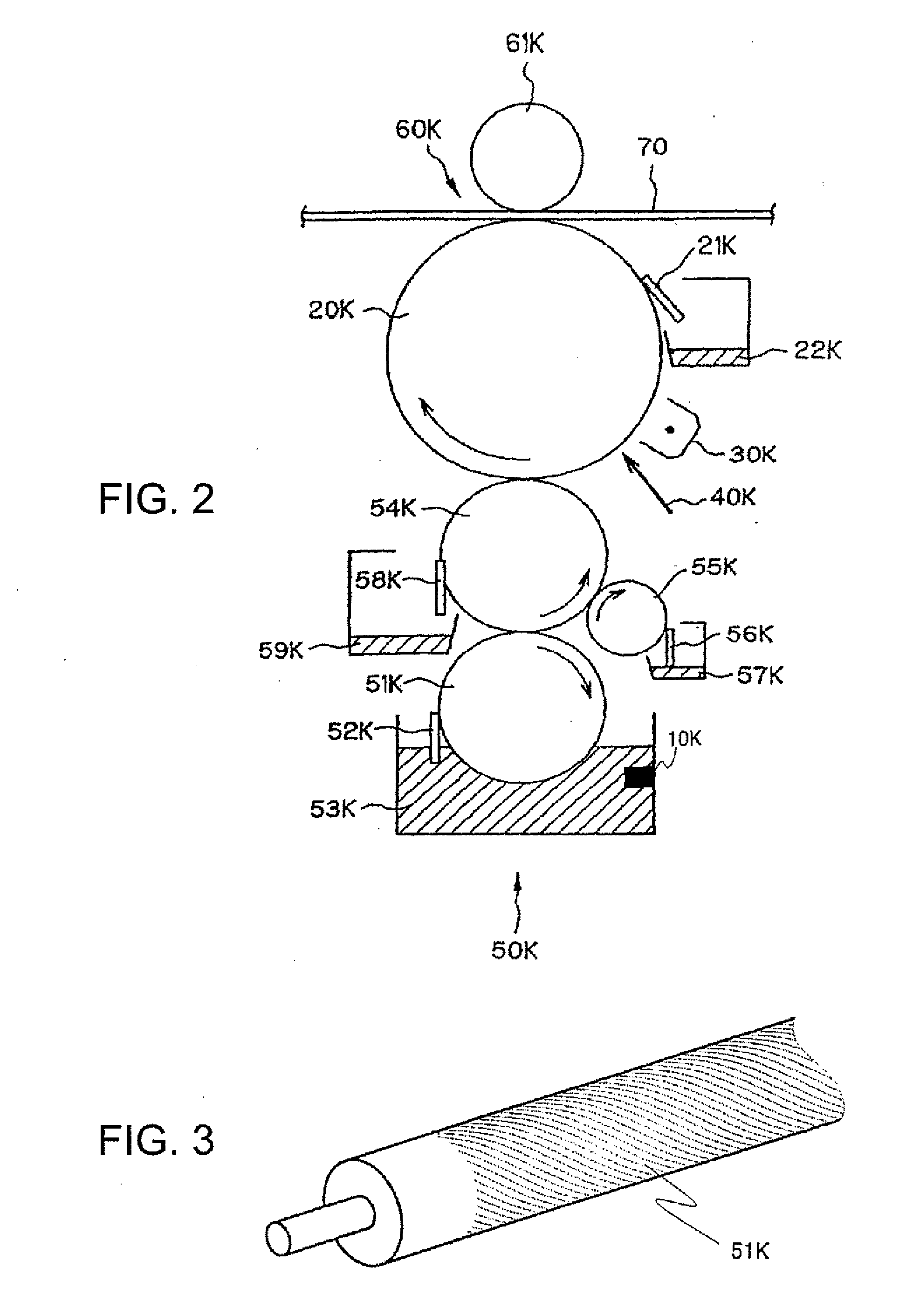
[0047]Embodiments of the invention are described by referring to the accompanying drawings. FIG. 1 is a diagram showing the main configuration of an image forming apparatus in an embodiment of the invention.

[0048]An intermediate transfer belt 70 is an endless belt being placed across a belt drive roller 82 and a follower roller 85. The intermediate transfer belt 70 is rotate-driven while coming in contact with photosensitive elements 20Y, 20M, 20C and 20K. The intermediate transfer belt 70 configures, respectively, primary transfer units 60Y, 60M, 60C, and 60K together with primary transfer backup rollers 61Y, 61M, 61C, and 61K and the photosensitive elements 20Y, 20M, 20C, and 20K. With the primary transfer units 60Y, 60M, 60C and 60K, liquid toners of four colors are sequentially transferred, one on the other, onto the intermediate transfer belt 70 so that a full-color liquid toner image is formed. In the embodiment, used is a liquid developer being a result of dispersing toner pa...


PUM


Abstract

An image development apparatus, including: a developer carrier that carries thereon a liquid developer being a carrier solution including dispersed toner particles each made of a coloring agent and a resin; a developer supply member that supplies the developer to the developer carrier; a developer compression member that is opposing the developer carrier, and compresses any solid content of the developer to a side of the developer carrier through application of an electric field to the developer on the developer carrier supplied by the developer supply member; a developer compression member voltage application unit that applies a voltage to the developer compression member; and a current detection unit that detects a current flowing from the developer compression member to the developer carrier.

Description

BACKGROUND[0001]1. Technical Field[0002]The entire disclosure of Japanese Patent Application Nos: 2006-262537, filed Sep. 27, 2006 and 2006-262538, filed Sep. 27, 2006 and 2006-262649, filed Sep. 27, 2006 and 2007-178252, filed Jul. 6, 2007 are expressly incorporated by reference herein.[0003]The present invention relates to an image development apparatus using a liquid toner being a result of dispersing toner particles in a carrier solution, an image forming apparatus using the image development apparatus, an image development method, and an image forming method using the image development method.[0004]2. Related Art[0005]A previous image forming method using a liquid toner is described in Patent Document 1 (JP-A-2002-278291). Patent Document 1 describes an image forming method of using a developing roller carrying thereon a liquid toner for latent image development on a photosensitive element. In the method, a compression roller is used for compressing the liquid toner on the deve...

Claims


Application Information

Patent Timeline
IPC IPC(8): G03G13/06G03G15/10
CPCG03G15/104G03G2215/0869G03G2215/0626
Inventor NAKAMURA, MASAHIDEFUKAZAWA, MASAHIROTERAOKA, TSUTOMUIKUMA, KEN
Owner SEIKO EPSON CORP
Learn More