Novel coupling film separating method and device used in gas separation

A gas separation membrane and gas separation technology, applied in separation methods, dispersed particle separation, chemical instruments and methods, etc., can solve the problems of poor chemical stability, complexity of olefin carriers, and restricting the development of industrialization process.

Inactive Publication Date: 2007-10-17
TIANBANG NAT ENG RES CENT OF MEMBRANE TECH
View PDF0 Cites 14 Cited by
  • Summary
  • Abstract
  • Description
  • Claims
  • Application Information

AI Technical Summary

Problems solved by technology

In its U.S. Patent 5670051 (1997), Pinnau et al. put Ag + Embedded in a polymer membrane to form a so-called solid polymer electrolyte membrane, but the poor chemical stability of olefin supports seriously hinders the industrialization of this separation process
At the same time, Nymeijer et al pointed out that Ag + For trace H 2 Gases such as S and acetylene are more sensitive, including Ag + The solid polymer electrolyte membran...

Method used


Image

  • Novel coupling film separating method and device used in gas separation
  • Novel coupling film separating method and device used in gas separation
  • Novel coupling film separating method and device used in gas separation

Examples


Embodiment 1

[0061] Example 1 Theoretical simulation of the separation performance of ethylene / ethane passing through the separation unit

[0062] The composite gas separation membrane with polyetherimide (PEI) porous membrane as the base membrane and polydimethylsiloxane (PDMS) as the composite separation layer material is used as the gas separation membrane of the gas separation membrane bag. The carrier solution is 4M AgNO 3 solution. The loss and renewal of the carrier solution is not considered in the simulation, and the flow velocity of the carrier solution in the channel of the carrier solution is 0m / s. The raw gas is pure ethylene and ethane. Separation performance of composite gas separation membranes with ethylene and ethane in AgNO 3 The physical properties in the carrier solution are shown in Table 1. The thickness (d) of the carrier solution channel was 300 μm. Ethylene is carried out in the form of dissolution and diffusion in the composite gas separation membrane, in th...

Embodiment 2

[0063] Example 2 Sandwich gas separation membrane bag

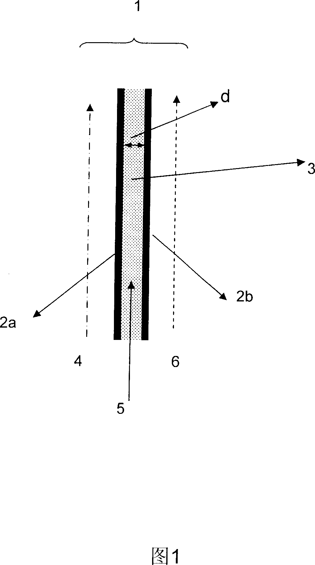
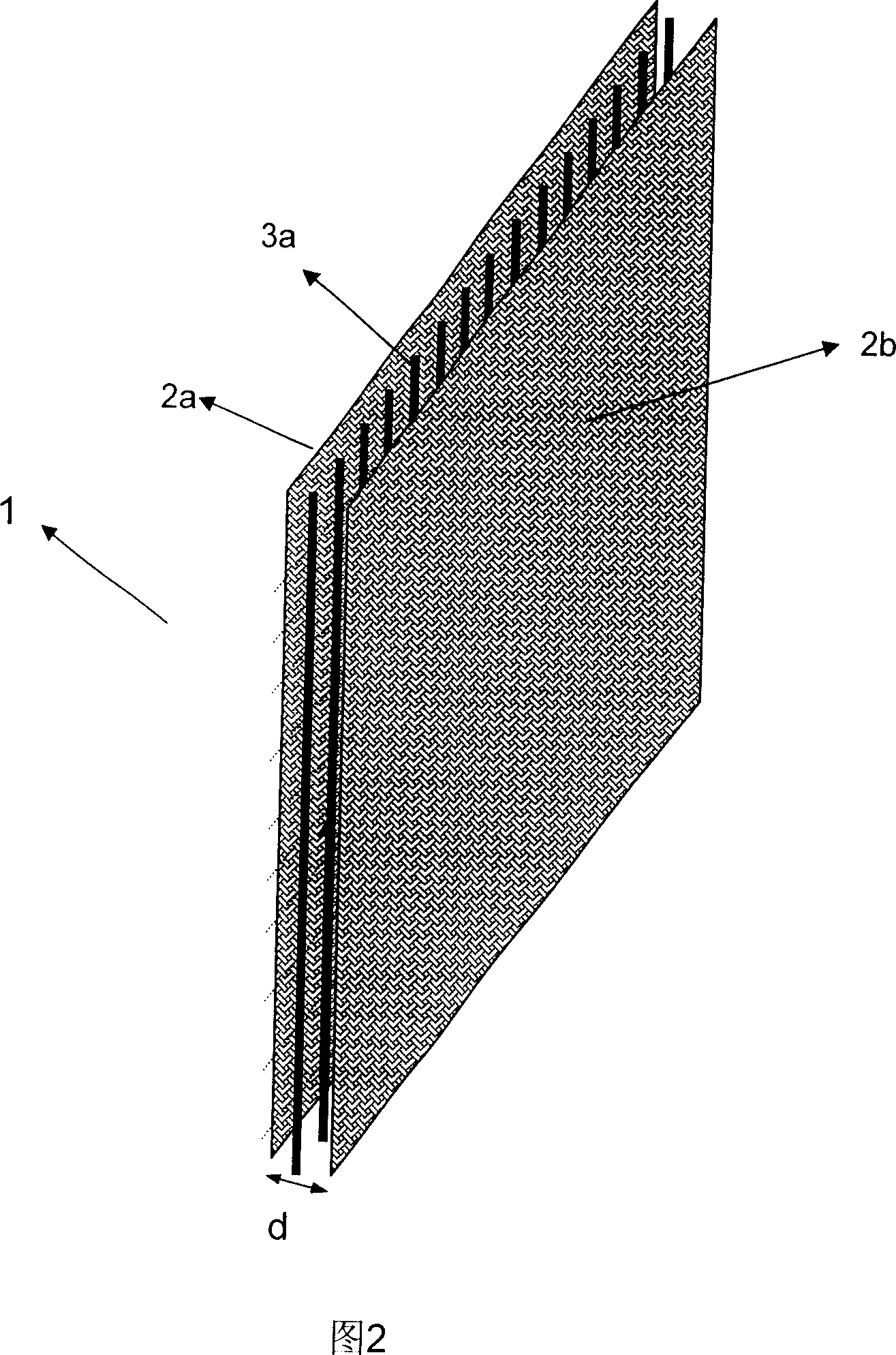
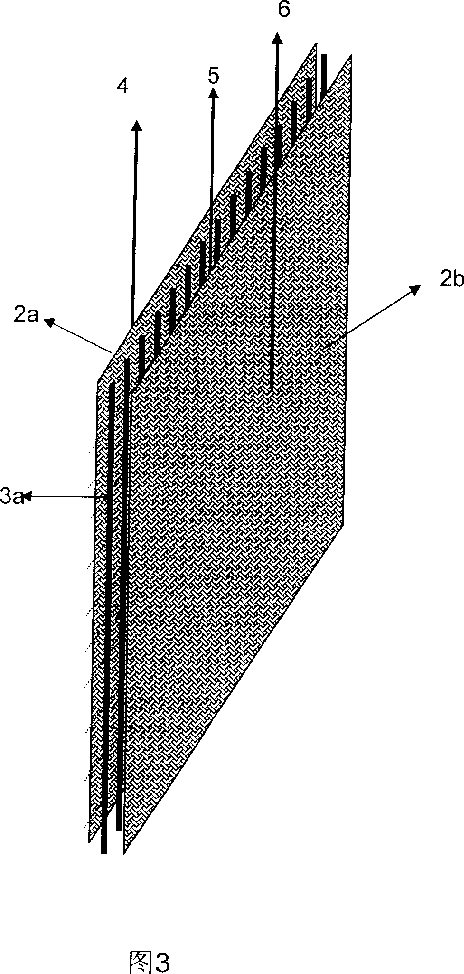
[0064] In the present invention, the gas separation membrane bag is defined as a basic separation unit, forming a sandwich structure of gas separation membrane-carrier solution-gas separation membrane. Figure 9 depicts a schematic diagram of the structure of a basic gas separation membrane bag. A carrier solution channel with a certain thin layer thickness (d) is formed between the gas separation membranes 2a and 2b, and the carrier solution flow 5 flows in the channel at a certain speed to replenish and renew the carrier solution. A spacer 3a of a certain thickness may be placed between the gas separation membranes to support the gas separation membranes. At the same time, the thickness of the carrier solution, that is, the distance (d) between the gas separation membranes can be adjusted by the thickness of the spacer 3a between the gas separation membranes. The carrier solution 3 is filled in the space between the ga...

Embodiment approach 3

[0068] Embodiment 3 Separation device

[0069] Several gas separation membrane bags can be stacked to produce a plate-and-frame membrane separation unit or a roll-type membrane separation unit. A certain distance is maintained between adjacent gas separation membrane bags to form passages for raw gas or permeate gas. Figure 13 illustrates a superimposed schematic diagram of the membrane elemental separation elements for the preparation of the membrane separation unit. The M th gas separation membrane bag and the M+1 th gas separation membrane bag form a raw gas channel 7 . Its spacing (df) can be adjusted through the net or frame. The M+1th gas separation membrane bag and the M+2th gas separation membrane bag form a permeate gas channel 8 . Its spacing (dp) can also be adjusted through a mesh or frame. The M+2 basic membrane separation element and the M+3 basic membrane separation element form the raw gas channel 7 . Raw material gas channels and permeate gas channels app...


PUM

PropertyMeasurementUnit
Thicknessaaaaaaaaaa
Thicknessaaaaaaaaaa

Abstract

The invention relates to a method for gas separating, a device thereof and a novel coupled film separation method for gas separating. The material gas is separated through a plurality of separation units, the material gas of each separation unit is firstly contacted with the gas separation film of one side, the gas component forming ligand structure with carrier solution by the form of improving transfer is firstly dissolving and diffusing in the gas separation film contacted therewith, then forms ligand structure with the carrier solution to pass the thin carrier solution and contact with the gas separation film at the other side by the form of improving transfer, and desorbs at the infiltration side by dissolving and diffusing in the gas separation film; the gas component in the material gas which can not form ligand structure with carrier solution is firstly dissolving and diffusing in the gas separation film contacted therewith, then contacts with the gas separation film at the other side by the form of dissolving and diffusing in the thin carrier solution, and desorbs at the infiltration side by dissolving and diffusing in the gas separation film to arrive at the purpose for separating the material gas. The separation method of the invention can satisfy the demand for the gas high pressure separating, avoid plastic effect, prevent wetness and leak of the film, and maintain long-time stability.

Description

Technical field: [0001] The present invention relates to a gas separation method, and also to a gas separation device. Background technique: [0002] Gas separation is a very important processing method in the chemical industry, especially olefin / alkane separation has always occupied a very important position in the chemical industry. Ethylene and propylene are chemical raw materials with the largest and second largest output in petrochemical industry. At present, the separation technologies of olefins / alkanes mainly include cryogenic rectification, pressure swing adsorption, lean oil absorption, extractive distillation, etc. These processes generally have poor selectivity, low separation coefficient and high energy consumption. At present, the raw materials for olefin production mainly come from crude oil (naphtha, diesel, propane, etc.) and natural gas (ethane, propane, etc.). Since olefins / alkanes have very similar boiling points, the distillation column used for separa...

Claims


Application Information

Patent Timeline
IPC IPC(8): B01D53/22
Inventor 任吉中王雁北邓麦村
Owner TIANBANG NAT ENG RES CENT OF MEMBRANE TECH
Why Eureka
Try Eureka