

Toner, production method thereof, toner container, developer, image forming apparatus and process cartridge using the same
- Summary
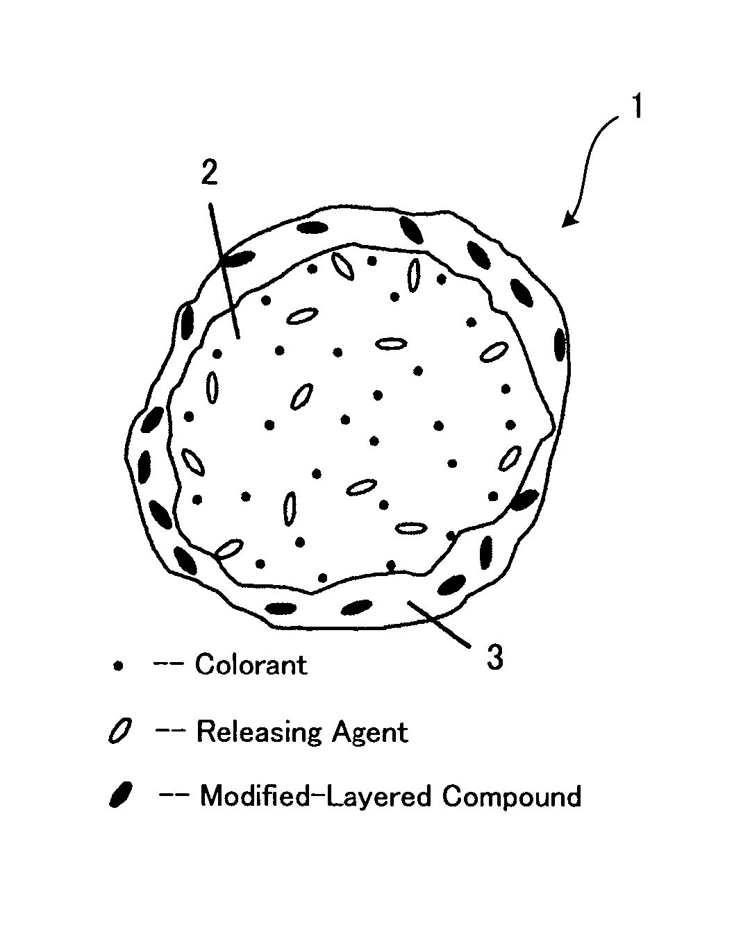
- Abstract
- Description
- Claims
- Application Information
AI Technical Summary
Benefits of technology
Problems solved by technology
Method used
Image

Examples
synthesis example 1
[0329]—Synthesization of Polyester Resin P-1—
[0330] Into a reaction container equipped with a cooling tube, a stirrer and a nitrogen introducing tube, 553 parts by mass of ethylene oxide (2 mol) adduct of bisphenol A, 196 parts by mass of propylene oxide (2 mol) adduct of bisphenol A, 220 parts by mass of terephthalic acid, 45 parts by mass of adipic acid and 2 parts by mass of dibutyl tin oxide were placed. They were reacted under an atmospheric pressure at 230° C. for 8 hours, and further reacted under a reduced pressure in the range of 10 mmHg to 15 mmHg at 230° C. for 5 hours. Then, 26 parts by mass of trimellitic anhydride was added into the reacted product, and the resulted mixture was further reacted under an atmospheric pressure at 180° C. for 2 hours. Thereby polyester resin (P-1) was obtained.
[0331] The thus obtained polyester resin (P-1) had a number average molecular weight of 2,200, a weight average molecular weight of 5,600, a glass transition temperature (Tg) of 43° ...
synthesis example 2
[0332]—Synthesization of Polyester Resin P-2—
[0333] Into the reaction container equipped with the cooling tube, the stirrer and the nitrogen introducing tube, 229 parts of ethylene oxide (2 mol) adduct of bisphenol A, 529 parts by mass of propylene oxide (3 mol) adduct of bisphenol A, 208 parts by mass of terephthalic acid, 46 parts by mass of adipic acid and 2 parts by mass of dibutyl tin oxide were placed. They were reacted under an atmospheric pressure at 230° C. for 8 hours, and further reacted under a reduced pressure in the range of 10 mmHg to 15 mmHg at 230° C. for 5 hours. Then, 44 parts by mass of trimellitic anhydride was added into the reacted product, and the resulted mixture was further reacted under an atmospheric pressure at 180° C. for 2 hours. Thereby polyester resin (P-2) was obtained.
[0334] The thus obtained polyester resin (P-2) had a number average molecular weight of 2,500, a weight average molecular weight of 6,700, a glass transition temperature (Tg) of 43° ...
synthesis examples 3 to 4
[0335]
[0336]—Resin Particulate (V-1) of Vinyl Copolymer—
[0337] Into the reaction container equipped with the cooling tube, the stirrer and the nitrogen introducing tube, 1.6 parts of dodecyl sodium sulfate and 502 parts of ion-exchanged water were placed. They were heated to 80° C., and then solution of 100 parts by mass of ion-exchanged water and 2.5 parts by mass of potassium peroxodisulfate which was dissolved into that ion-exchanged water was added. After 15 minutes the solution had been added, a solution dispersed using CLEARMIX (manufactured by M-Technique Co.) for 60 minutes was delivered by drops into the reaction container in 90 minutes. The dispersed solution was composed of 152 parts by mass of styrene monomer, 38 parts by mass of butyl acrylate, 10 parts by mass of methacrylic acid, 3.5 parts by mass of n-octylmercaptan and 4 parts by mass of layered inorganic mineral, montmorillonite (Clayton APA, manufactured by Southern Clay Products) in which at least a part thereof ...
PUM
| Property | Measurement | Unit |
|---|---|---|
| Fraction | aaaaa | aaaaa |
| Fraction | aaaaa | aaaaa |
| Fraction | aaaaa | aaaaa |
Abstract
Description
Claims
Application Information