
Refrigeration system fault detection and diagnosis using distributed microsystems

a distributed microsystem and refrigeration system technology, applied in the field of cooling systems, can solve the problems of delayed fault detection and correction, costly and time-consuming detection and diagnosis of system faults in commercial refrigeration systems, and potential damage to perishable objects, so as to prevent failure, prevent system deterioration, and prevent failure.

Inactive Publication Date: 2008-03-27
SIEMENS IND INC
View PDF12 Cites 46 Cited by
  • Summary
  • Abstract
  • Description
  • Claims
  • Application Information

AI Technical Summary

Benefits of technology

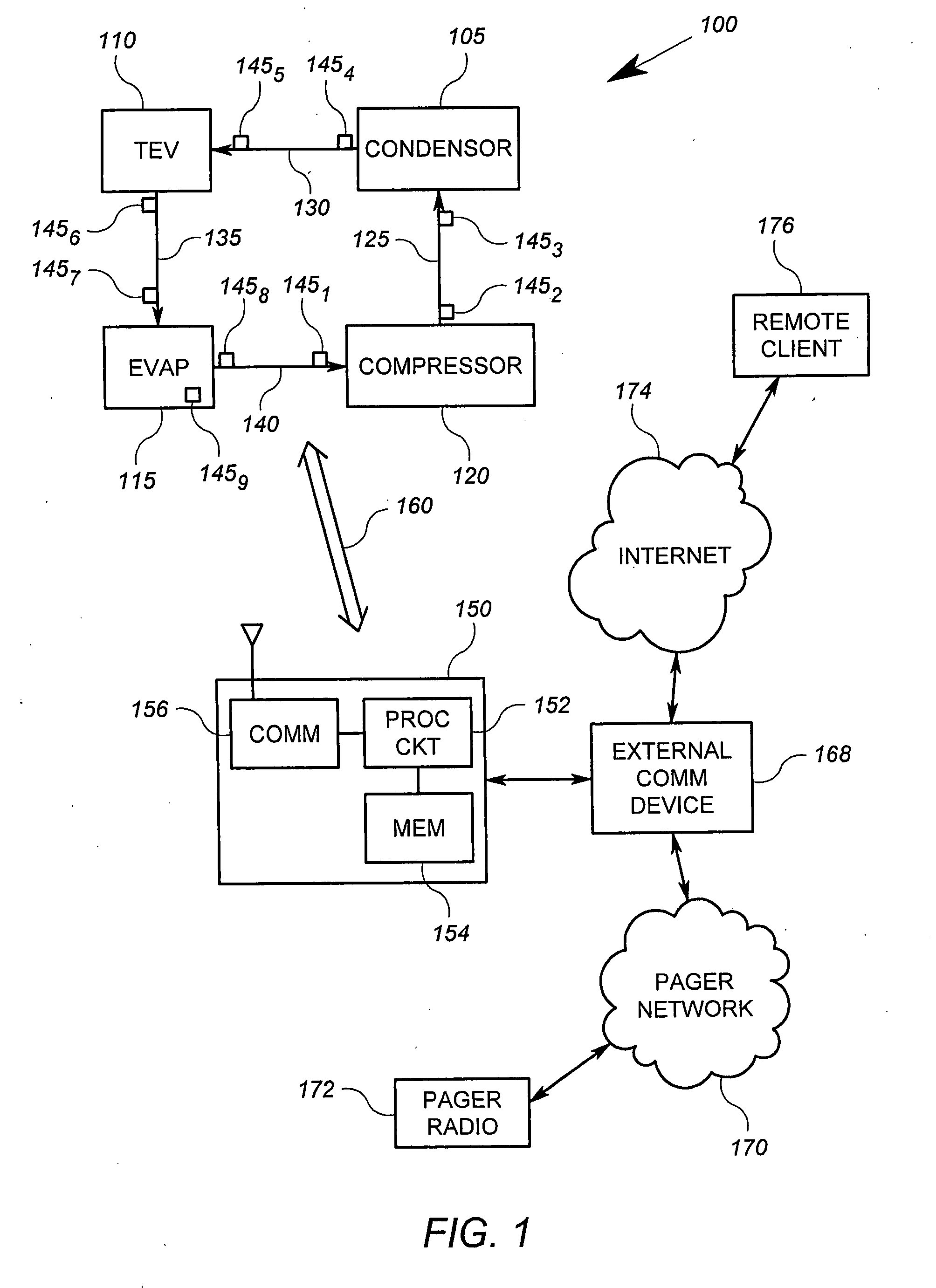
[0009]The present invention addresses the above mentioned issue by incorporating wireless microsystems sensors that may be readily and permanently installed in a cooling system. Wireless microsystem sensors may then be used to monitor a variety of conditions, including by way of example, pressure and temperature of refrigerant at various locations of the system. The data points may be used to detect and / or isolate failures within the system. In some systems, the data may merely be gathered for use by a technician for diagnosis. In other systems, data may be monitored automatically on an ongoing basis so that deterioration of system operation may be detected and failure prevented.
[0012]The use of wireless sensors to obtain data for automated analysis of refrigeration system parameters can provide advance warning of system faults as well as aid in diagnostics.

Problems solved by technology

One issue that arises is that detection and diagnosis of system faults in commercial refrigeration systems is costly and time consuming.
Typically, fault detection first begins when the cooling system fails.
Drawbacks of the current fault handling approaches include the potential damage to perishable objects attributable to delays in fault detection and correction.
In addition, the fault diagnosis itself is labor intensive and costly.

Method used


Image

  • Refrigeration system fault detection and diagnosis using distributed microsystems
  • Refrigeration system fault detection and diagnosis using distributed microsystems
  • Refrigeration system fault detection and diagnosis using distributed microsystems

Examples


Embodiment Construction

[0019]For the purposes of promoting an understanding of the principles of the invention, reference will now be made to the embodiments illustrated in the drawings and described in the following written specification. It is understood that no limitation to the scope of the invention is thereby intended. It is further understood that the present invention includes any alterations and modifications to the illustrated embodiments and includes further applications of the principles of the invention as would normally occur to one skilled in the art to which this invention pertains.

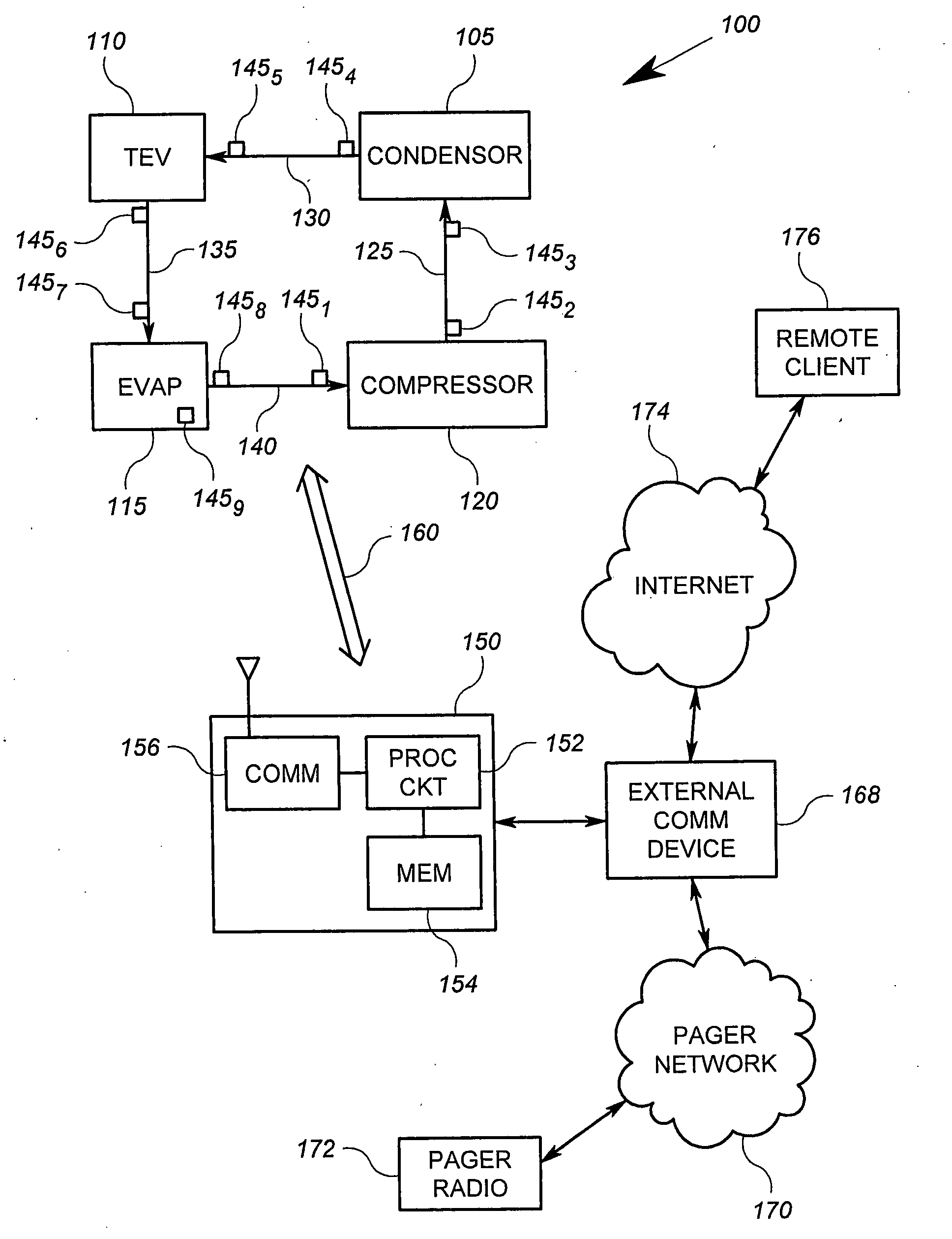
[0020]FIG. 1 shows a schematic diagram of a generalized refrigeration system 100 that includes an arrangement according to an embodiment of the invention. The refrigeration system 100 includes a condensor 105, a thermostatic expansion valve (TEV) 110, an evaporator 115, a compressor 120, a first refrigerant path 125, a second refrigerant path 130, a third refrigerant path 135 and a fourth refrigerant path 140. T...


PUM


Abstract

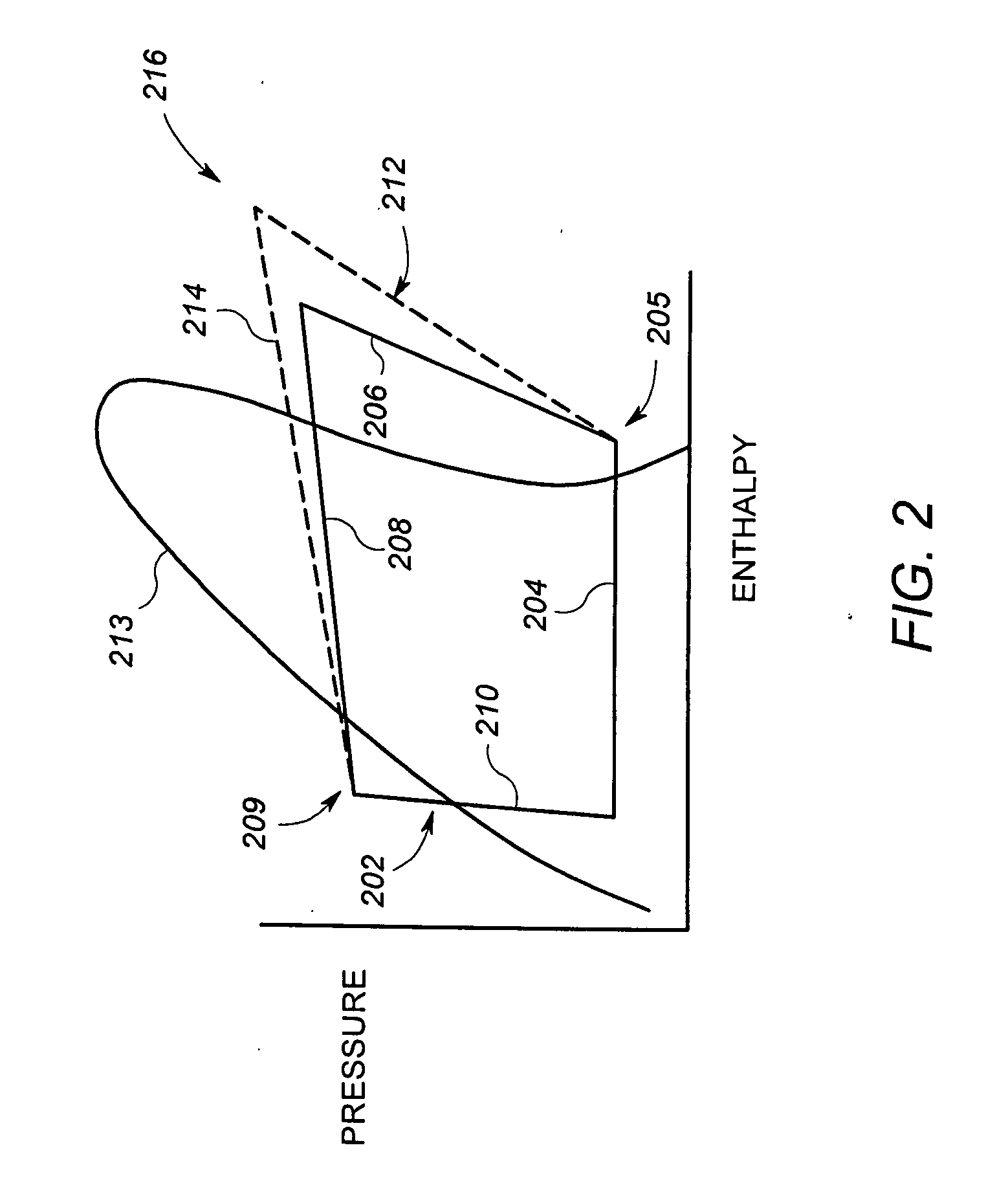
A method and / or apparatus determines whether a refrigeration (or other cooling) related system is operating within normal parameters by comparing reference data derived from ideal or normal conditions within the system. Data regarding the actual operating parameters of the system is provided via a set of microsystem sensors disposed throughout the refrigeration or cooling system. The sensors are in some embodiments wireless, and in some advantageous embodiments includes MEMs sensors.

Description

[0001]This application claims the benefit of U.S. Provisional Application Ser. No. 60 / 846,459, filed Sep. 22, 2006, U.S. Provisional Application Ser. No. 60 / 847,058, filed Sep. 25, 2006, U.S. Provisional Application Ser. No. 60 / 846,919, filed Sep. 25, 2006, all of which are incorporated herein by reference.CROSS-REFERENCE TO RELATED APPLICATIONS[0002]Cross-reference is made to U.S. patent application Ser. No. ______ (Atty Docket No. 1867-0147, Express Mail No. EV961072133US), filed Apr. 9, 2007, and U.S. patent application Ser. No. ______ (Atty Docket No. 1867-0148, Express Mail No. EV961072178US), filed Apr. 9, 2007.FIELD OF THE INVENTION[0003]The present invention relates to cooling systems, and more particularly, to commercial refrigeration systems and cooling subsystems of HVAC systems.BACKGROUND OF THE INVENTION[0004]Cooling systems are used for a variety of purposes, such as for refrigeration or air conditioning. One common type of cooling system is a vapor compression refrige...

Claims


Application Information

Patent Timeline
Patent Type & Authority Applications(United States)
IPC IPC(8): G05F1/00
CPCF04D27/001F25B49/005
Inventor PORTER, MICHAEL RAMEYROZSNAKI, JOSEPH JAMESAHMED, OSMAN
Owner SIEMENS IND INC
Learn More