Restoring a register renaming table within a processor following an exception

a register renaming and processor technology, applied in the field of data processing, can solve the problems of high storage space cost of register renaming and other problems, and achieve the effect of simple control logic, simple structure and simple control logi

Inactive Publication Date: 2008-03-27
ARM LTD
View PDF11 Cites 37 Cited by
  • Summary
  • Abstract
  • Description
  • Claims
  • Application Information

AI Technical Summary

Benefits of technology

[0012]One advantage of embodiments of the present invention is that information that is saved can be used to simply update a restore table, the restore table being in effect the register renaming table at the last resolved exception. Thus, every time an exception instruction is resolved it is updated with the necessary remapping of the registers. Thus, when an exception occurs it is a very simple matter to update the register renaming table by overwriting it with the restore

Problems solved by technology

This can cause problems if the data used by these instructions is stored in a very limited register set as a value stored in one register may be overwritten before it is used by another instruction.
This leads to errors.
As the remapping is dependent on t

Method used


Image

  • Restoring a register renaming table within a processor following an exception
  • Restoring a register renaming table within a processor following an exception
  • Restoring a register renaming table within a processor following an exception

Examples


Embodiment Construction

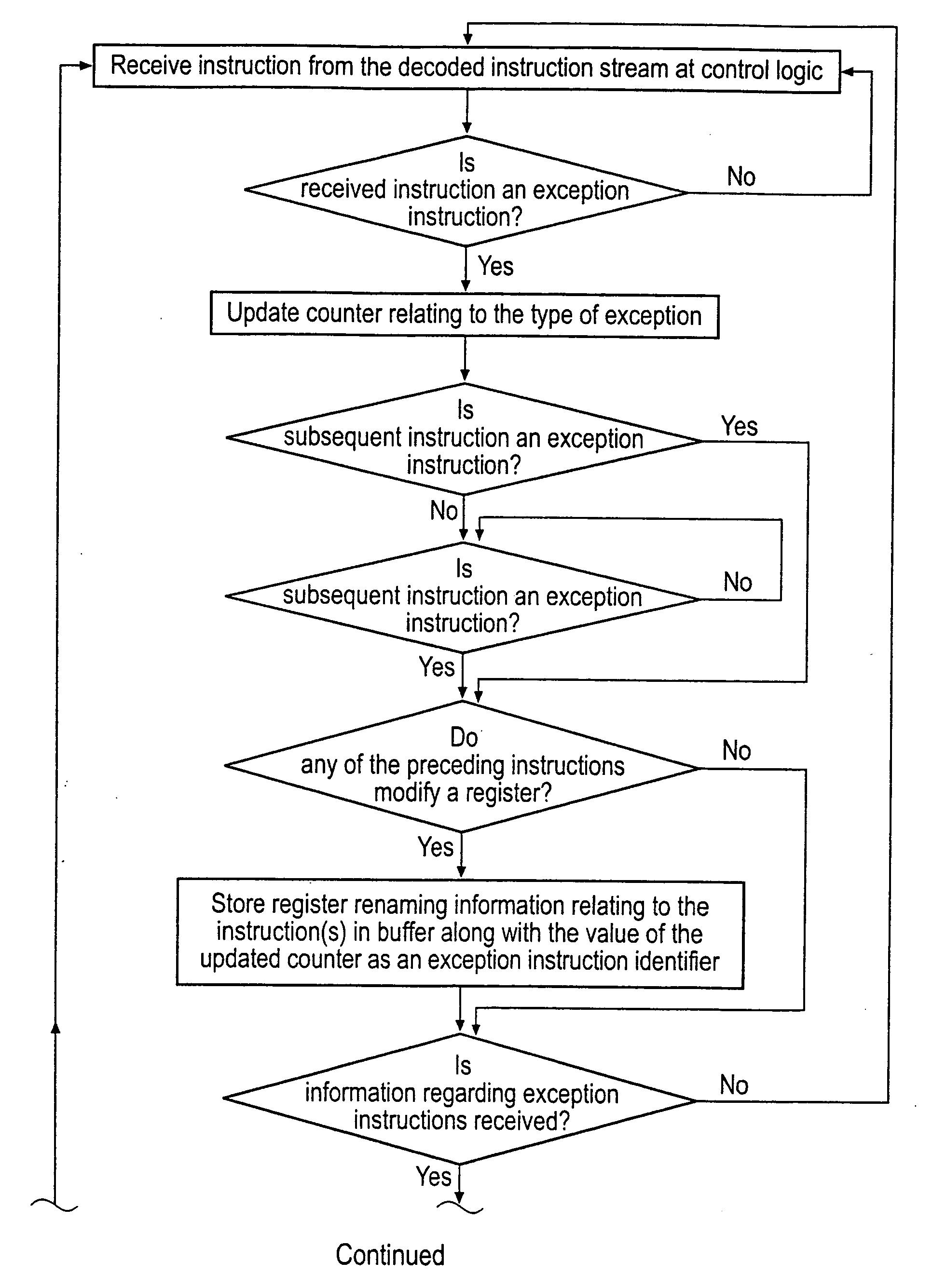
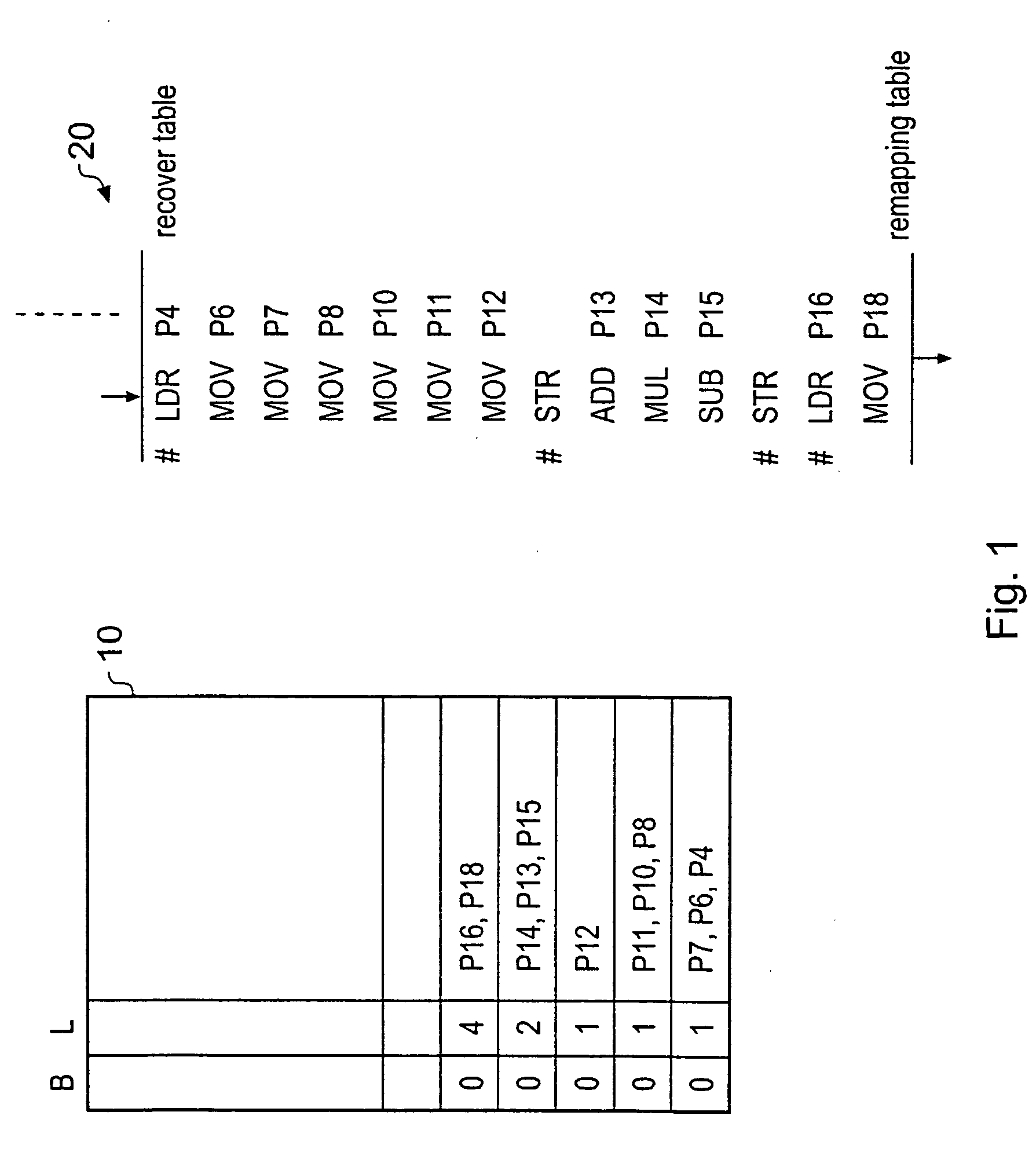
[0043]FIG. 1 shows a buffer 10 operable to store register renaming data that is needed to be able to restore a register renaming table if an exception occurs. FIG. 1 also shows an example stream of instructions 20, this stream of instructions was decoded in the direction of the arrow (that is the instruction at the top of the list LDR P4 was before MOV P6 in the instruction stream) and was then forwarded to register renaming logic, where the mapping between architectural registers and physical registers is performed, sequentially for each decoded instruction in the decoded instruction stream. The decoded instruction stream is shown as instructions with their remapped registers. Thus, P4, P6 etc. refer to physical registers present in the silicon, that the instruction shown write data values to. The portion of the instruction stream illustrated are the instructions that lie between the decoded instruction most recently remapped by the register remapping or renaming table and the deco...


PUM


Abstract

Control logic for storing values relating to unresolved exception instructions within a buffer to enable a register renaming table within a processor to be restored following an exception is disclosed. The processor is operable to process a stream of instructions from an instruction set, the instruction set comprising exception instructions and non-exception instructions, exception instructions being instructions that may generate an exception and non-exception instructions being instructions that execute in a statically determinable way. The processor comprises a physical set of registers operable to store data values being processed by the processor; and register renaming logic operable to receive a stream of decoded instructions and to map for each decoded instruction within the stream of decoded instructions, registers from an architectural set of registers associated with the instruction set to registers within the physical set of registers in dependence upon renaming values stored in the register renaming table; the control logic comprising a buffer and being operable: to identify exception and non-exception instructions within the decoded instruction stream and to group any non-exception instructions with a closest preceding exception instruction; to store in the buffer, register renaming values relating to any registers whose data values are modified by the group of instructions and which are renamed by the register renaming logic as a bundle of register renaming values associated with the exception instruction.

Description

BACKGROUND OF THE INVENTION[0001]1. Field of the Invention[0002]The field of the invention relates to data processing and in particular to register renaming in a CPU.[0003]2. Description of the Prior Art[0004]It is known to provide processors which process instructions from an instruction set specifying an architectural set of registers using a physical set of registers that is larger than the architectural set. This is a technique that has been developed to try to avoid resource conflicts due to instructions executing out of order in the processor. In order to have compact instruction encodings most processor instruction sets have a small set of register locations that can be directly named. These are often referred to as the architecture registers and in many ARM® (registered trade mark of ARM Ltd Cambridge UK) RISC instruction sets there will be 32 architecture registers.[0005]When instructions are processed different instructions take different amounts of time. In order to speed...

Claims


Application Information

Patent Timeline
IPC IPC(8): G06F7/38
CPCG06F9/30145G06F9/3863G06F9/384G06F9/3836
Inventor LATAILLE, NORBERT BERNARD EUGENEBEGON, FLORENTAIRAUD, CEDRIC DENIS ROBERTVINCENT, MELANIE
Owner ARM LTD
Why Eureka
Try Eureka