Roller Element

a technology of rollers and elements, applied in the direction of bearings, driving chains, chain elements, etc., can solve the problems of not being able to be utilized in materials handling technology in an efficient manner, reducing friction, and moving loads with as little force and friction, etc., to achieve low friction, high load, and suitability for materials handling technology

Inactive Publication Date: 2008-04-03
WRH WALTER REIST HLDG
View PDF14 Cites 26 Cited by
  • Summary
  • Abstract
  • Description
  • Claims
  • Application Information

AI Technical Summary

Benefits of technology

[0009]It is therefore the objective of the invention to create a roller element, which is suitable for utilization in materials handling technology. In particular, it is to make possible a supported relative movement of two bodies with a low friction and wi

Problems solved by technology

In the case of bearings, there is among others the problem that loads are to be moved with an as low an expenditure of force and with little friction.
The problem of the minimization of friction, however, remains present and is now transferred to the bearing support of the wheels.
The mentioned devices from

Method used


Image

  • Roller Element
  • Roller Element
  • Roller Element

Examples


Embodiment Construction

[0075]The reference marks used in the drawings and their significance are listed in summary in the list of reference marks. In principle, in the Figures the same parts are marked with the same reference marks.

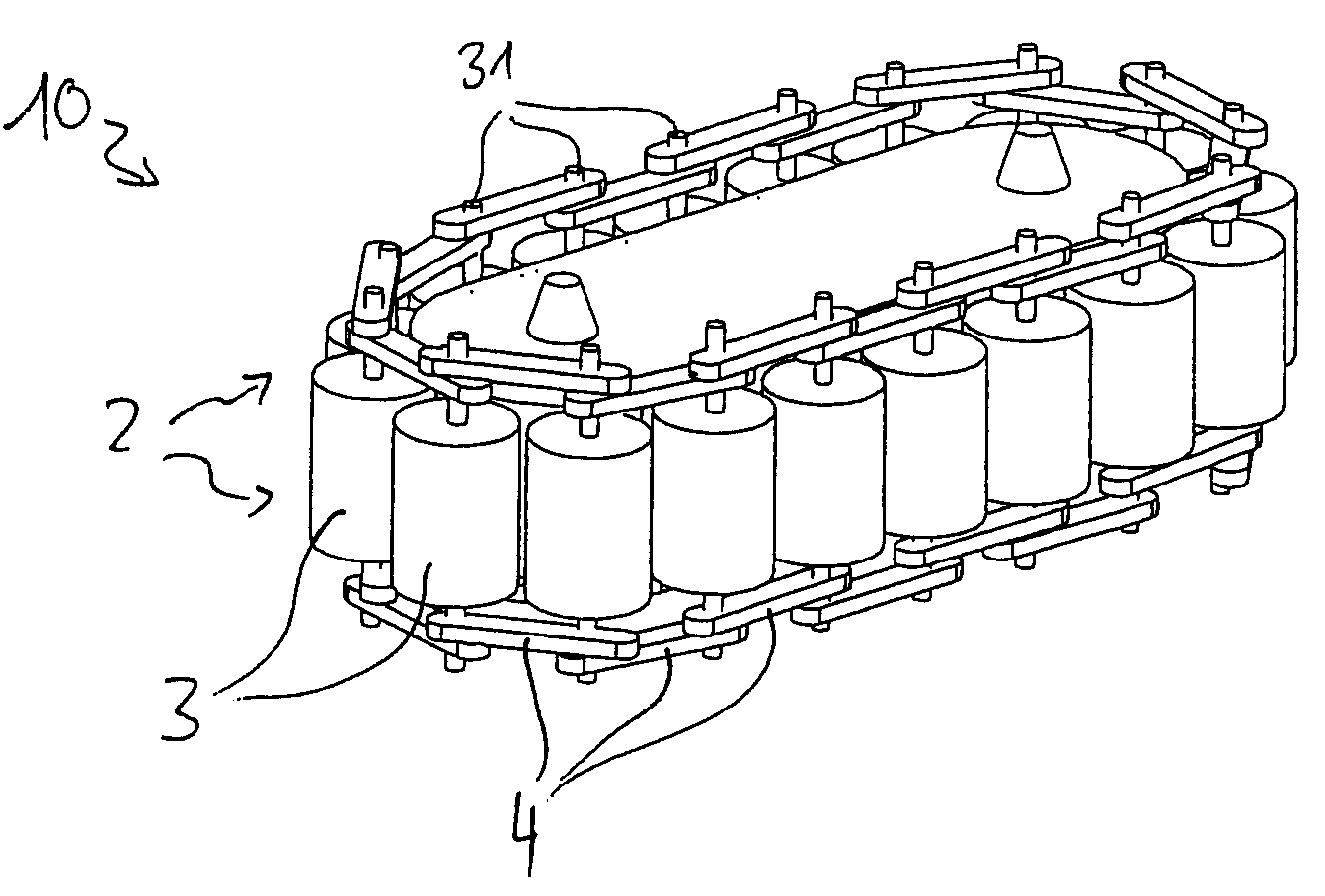
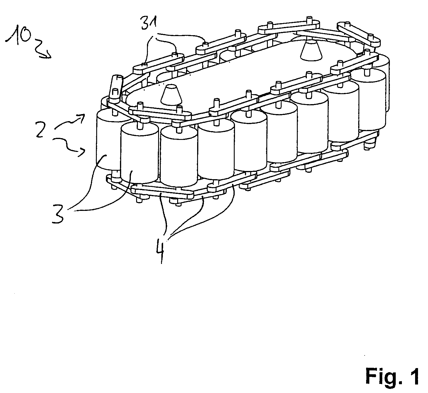
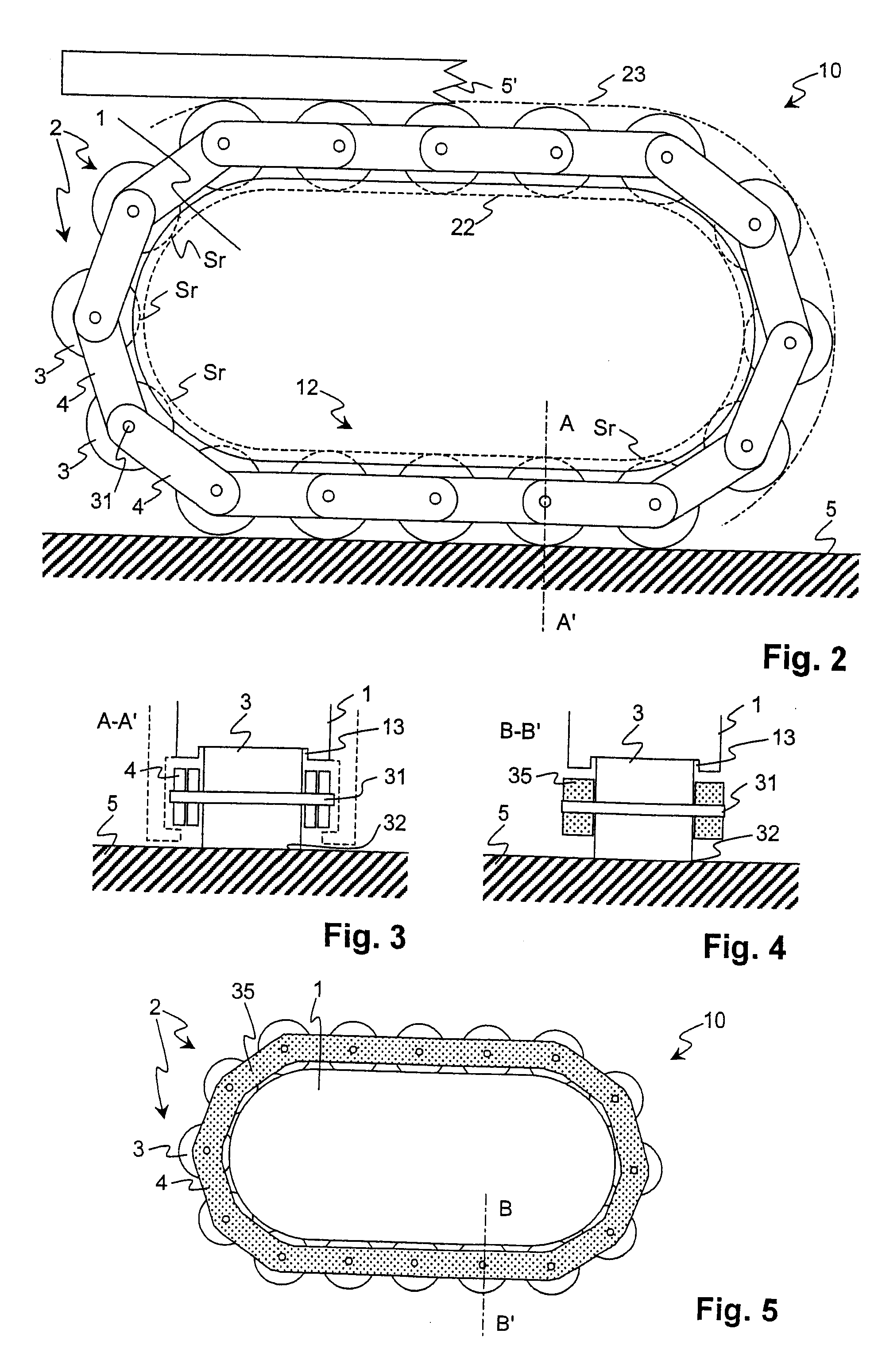
[0076]FIG. 1 depicts a perspective view and FIG. 2 schematically a side view of a roller element 10 in accordance with a preferred embodiment of the invention. The roller element 10 comprises a central body and a roller unit 2 circulating around it. The roller unit 2 consists of a plurality of rollers 3, the bearing axles 31 of which are connected together through chain link plates 4.

[0077]The chain link plates 4, together with the rollers 3, form a roller chain. The diameters of the rollers 3 in doing so are so large relative to the chain link plates 4, that the rollers 3 protrude beyond the chain link plates 4 inwards as well as outwards in radial direction. With this, a side of the totality of the rollers 3 forms an internal side 22 of the roller unit 2. Correspondingly, a s...


PUM

PropertyMeasurementUnit
Shapeaaaaaaaaaa
Circumferenceaaaaaaaaaa
Plasticityaaaaaaaaaa

Abstract

A roller element (10) is provided which has a central body (1) and a roller unit (2). The roller unit (2) is mounted so as to circulate on a non-circular race (21) about the central body (1) and so as to be mobile with respect to the central body (1) by the rolling movement of the rollers (3) of the roller unit (2) on the central body (1). The rollers (3) are configured as balls or substantially cylindrical elements. A peripheral surface of the rollers (3), for a substantial part, is shaped as a rolling surface that corresponds to the central body (1) and for rolling off on the central body (1). The elements of the roller unit (2) have play in relation to one another and/or the roller unit has play regarding its mobility in relation to the central body (1).

Description

BACKGROUND OF THE INVENTION[0001]1. Field of the Invention[0002]The invention is related to the field of roller bearings and concerns a roller element.[0003]2. Description of Related Art[0004]In the case of bearings, there is among others the problem that loads are to be moved with an as low an expenditure of force and with little friction. In doing so, the construction of conveying means is to be as simple as possible. For achieving of a linear, rotary or any other guided movement between bodies, wheels are utilised, which are attached to a first body and which roll on a second body. In case of high loads the number of wheels is increased. The problem of the minimization of friction, however, remains present and is now transferred to the bearing support of the wheels.[0005]In the patent document GB 403 082 from the year 1932, an arrangement for the utilization in travelling trolleys and undercarriages is demonstrated, in the case of which several respectively axially connected pair...

Claims


Application Information

Patent Timeline
IPC IPC(8): B21L9/02F16G13/06B65G7/00B65G7/04B65G17/20F16C29/06F16C33/38F16C33/50F16C33/52
CPCB65G7/04B65G17/20F16C33/3812Y10T29/49641F16C33/52F16C19/502F16C29/0619F16C33/50
Inventor REIST, WALTER
Owner WRH WALTER REIST HLDG
Why Eureka
Try Eureka