Thermoelectric air conditioning unit & a thermoelectric air conditioner thereof

Inactive Publication Date: 2008-04-03
CAO AI GUO
View PDF5 Cites 10 Cited by
  • Summary
  • Abstract
  • Description
  • Claims
  • Application Information

AI Technical Summary

Benefits of technology

[0020]When compared to the prior art, the present invention by having the insulation heat transfer coated layer respectively applied on the sides respectively of the heat exchanger and the heat transfer water tank that are attached to the thermoelectric component to substitute the insulation heat transfer plate disposed in the prior art allows direct installation of the thermoelectric component to where between the heat exchanger and the heat transfer water tank to avoid thermal loss of 1˜2□ by shortening the range between the heat exchanger and the thermoelectric component and the range between the heat transfer water tank and the thermoelectric component to upgrade the energy efficiency ratio (EER) of the thermoelectric air conditioning unit and the thermoelectric air conditioner containing the thermoelectric air conditioning unit.
[0021]Those independent waterways connected in sequence with the head and the tail of each water way disposed in a cabinet of the heat transfer water tank of the thermoelectric air co

Problems solved by technology

However, the ceramic plate is found with flaws including low efficient ratio of heat or cold transfer and higher energy consumption due to that there will be a thermal loss of 1˜2□ as the temperature of the thermoelectric component after making cool air is transferred through the insulation heat transfer plate to the heat exchanger.
It is true that the heat sink performance is better

Method used


Image

  • Thermoelectric air conditioning unit & a thermoelectric air conditioner thereof
  • Thermoelectric air conditioning unit & a thermoelectric air conditioner thereof
  • Thermoelectric air conditioning unit & a thermoelectric air conditioner thereof

Examples


Embodiment Construction

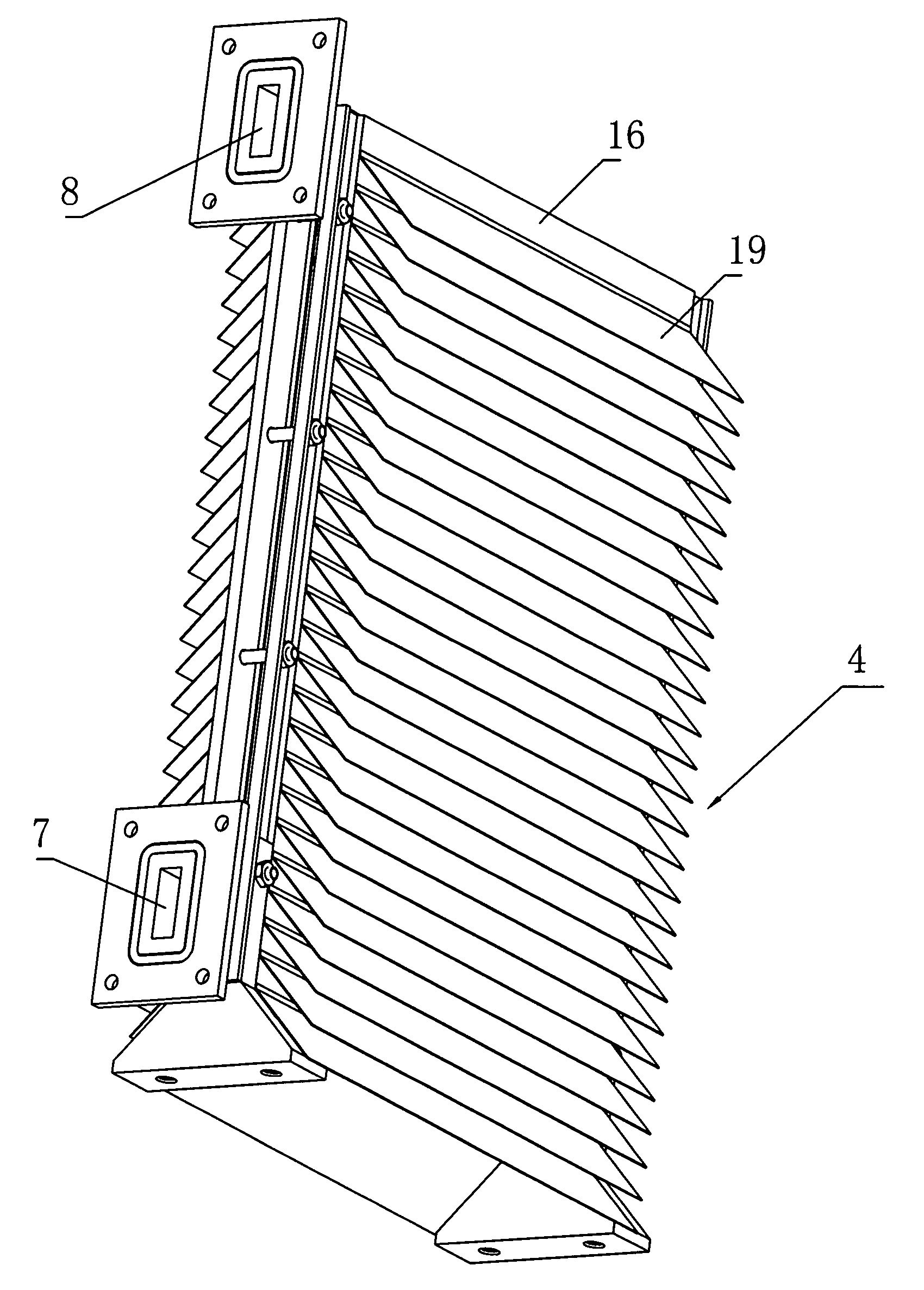
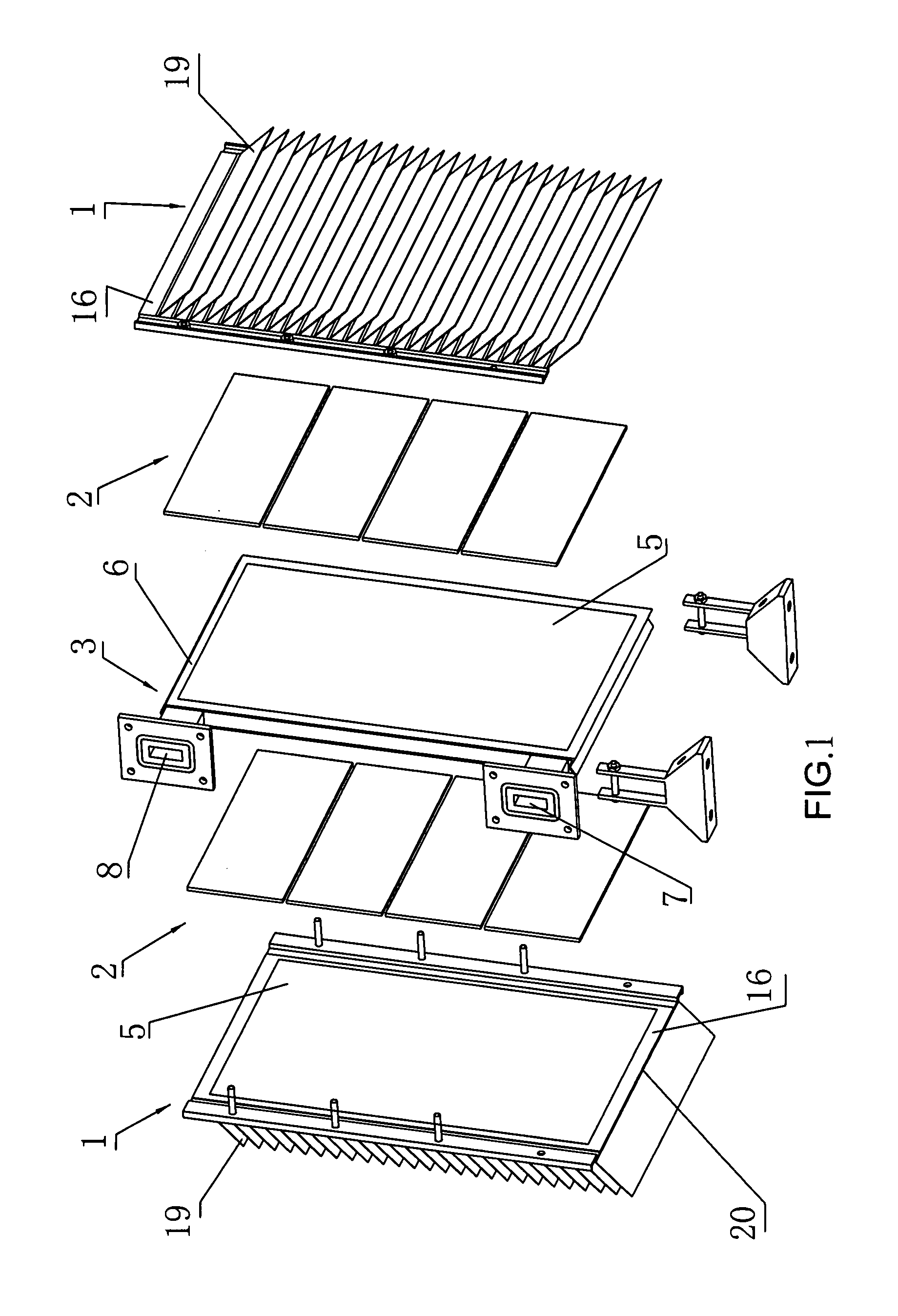
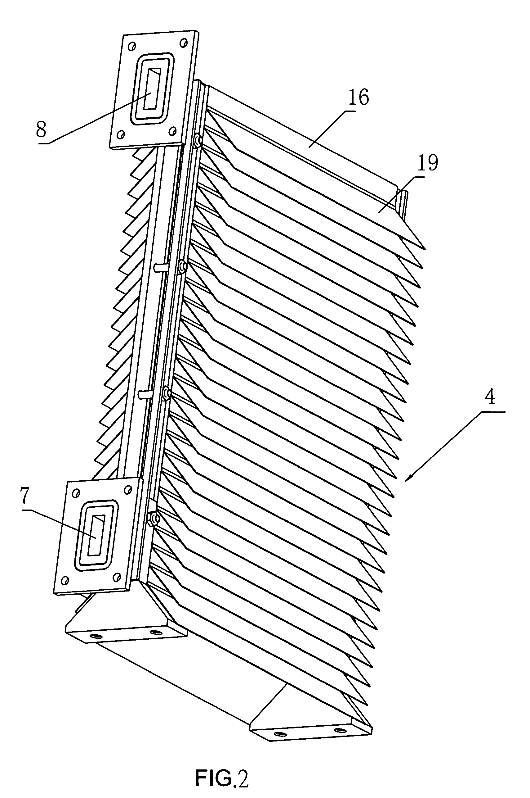
[0029]Referring to FIGS. 1 through 4, a thermoelectric air conditioning unit 4 of the present invention is comprised of two thermoelectric components 2, two heat exchangers 1 to transfer hot air or cool air radiated from those two thermoelectric components 2 to an space where hot air or cool air is demanded, and one heat transfer water tank 3 to carry away the hot air or cool air radiated from those two thermoelectric components 2. Wherein the heat transfer water tank 3 is sandwiched by those two thermoelectric components 2 and an electricity of those two thermoelectric components 2 is the same as that on their respectively sides that are adhered to the heat transfer water tank 3. That is, when the thermoelectric components 2 are conducted through, both thermoelectric components 2 are the same hot end or cool end as that of the sides where both thermoelectric components 2 are respectively adhered to heat transfer water tank (whereas the thermoelectric component is comprised of a the...


PUM


Abstract

A thermoelectric air conditioning unit and a thermoelectric air conditioner containing the unit; the unit includes thermoelectric component and heat exchanger; the heat exchanger is provided with heat transfer plate; multiple heat sink fins are disposed on one side of the heat transfer plate and the other side of the heat transfer plate is adhered to the thermoelectric component; another side of the component is attached with a water tank; the component is secured at where between the exchanger and the tank; the exchanger and the tank are respectively coated on one side an insulation heat transfer layer; the air conditioner is provided with an outer casing containing multiple thermoelectric air conditioning units; a fan is fixed at the outer casing; heat loss is reduced for 1˜2 □ due to that the coated layer that substitutes a heat transfer plate so to upgrade energy efficiency ratio of the thermoelectric air conditioning unit and that of the thermoelectric air conditioner containing the unit.

Description

BACKGROUND OF THE INVENTION[0001](a) Field of the Invention[0002]The present invention is related to an air conditioning system, and more particularly, to a thermoelectric air conditioning unit and a thermoelectric air conditioner containing the thermoelectric air conditioning unit.[0003](b) Description of the Prior Art[0004]In general, thermoelectric air conditioning is more environment-friendly and demands less in manufacturing workmanship among the technical fields of cooling and air conditioning.[0005]Thermoelectric air conditioning systems generally available in the market are essentially comprised of a thermoelectric component and a heat exchanger to transfer hot air or cool air to a space that needs to have warmer air or cooler air. The heat exchanger is provided with a heat transfer plate, multiple heat sink fins are vertically secured to one side of the heat transfer plate; another side of the heat transfer plate of the heat exchanger is adhered to a surface of one side of ...

Claims


Application Information

Patent Timeline
IPC IPC(8): F25B21/02
CPCF25B2321/023F25B21/02
Inventor CAO, AI GUO
Owner CAO AI GUO
Why Eureka
Try Eureka