Valve controller

a valve controller and valve technology, applied in the direction of valve operating means/releasing devices, service pipe systems, transportation and packaging, etc., can solve the problems of complex installation and maintenance problems over the life of the actuator

Inactive Publication Date: 2008-04-03
WESTLOCK CONTROLS
View PDF12 Cites 15 Cited by
  • Summary
  • Abstract
  • Description
  • Claims
  • Application Information

AI Technical Summary

Benefits of technology

[0004]The valve controller may have an enclosure with a visual indicator mounted thereon. The visual indicator provides a brightly colored vain to indicate the valve position (e.g. open or closed). The enclosure houses a cylinder having an internal cavity configured to receive the actuator shaft. When the stroke of an actuator shaft is activated in response to a signal to open or close the valve, the shaft vertically traverses at least a portion of the vertical length of the cylinder. A plunger disposed within the cylinder engages a first end of the actuator shaft. The plunger is forced upward by the actuator shaft and engages grooves in the cylinder cavity. The vertical distance the plunger traverses within the internal cavity corresponds to the distance traversed by the actuator shaft within the cylinder cavity which also corresponds to the operating stroke of the actuator shaft. The present invention avoids the need for a mechanical connection between the actuator shaft and the controller.

Problems solved by technology

This mechanical connection causes installation complexity and maintenance problems over the life of the actuator.

Method used


Image

  • Valve controller
  • Valve controller
  • Valve controller

Examples


Embodiment Construction

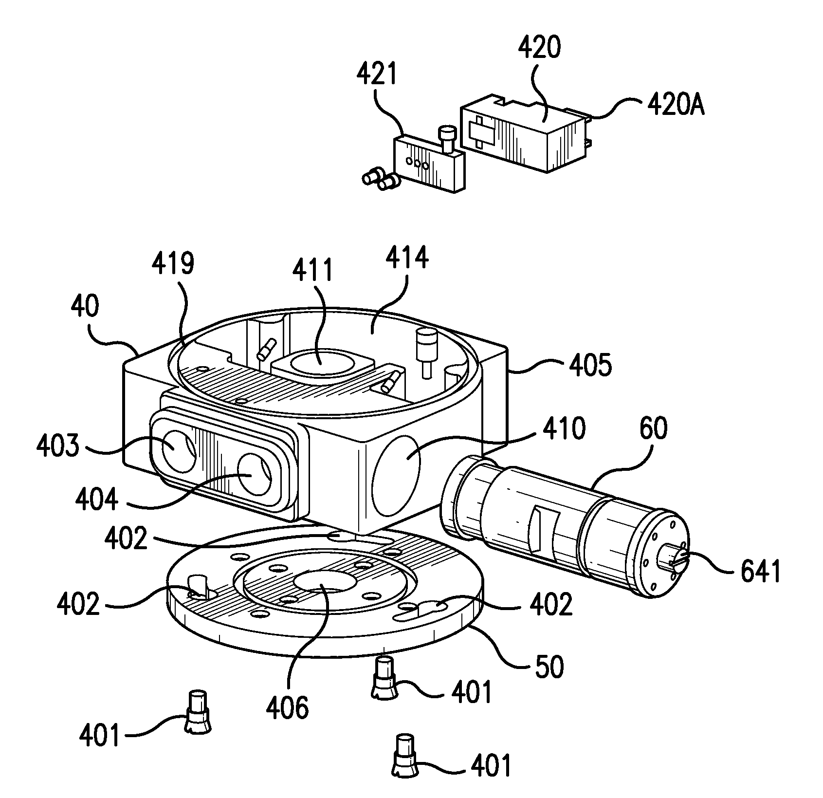
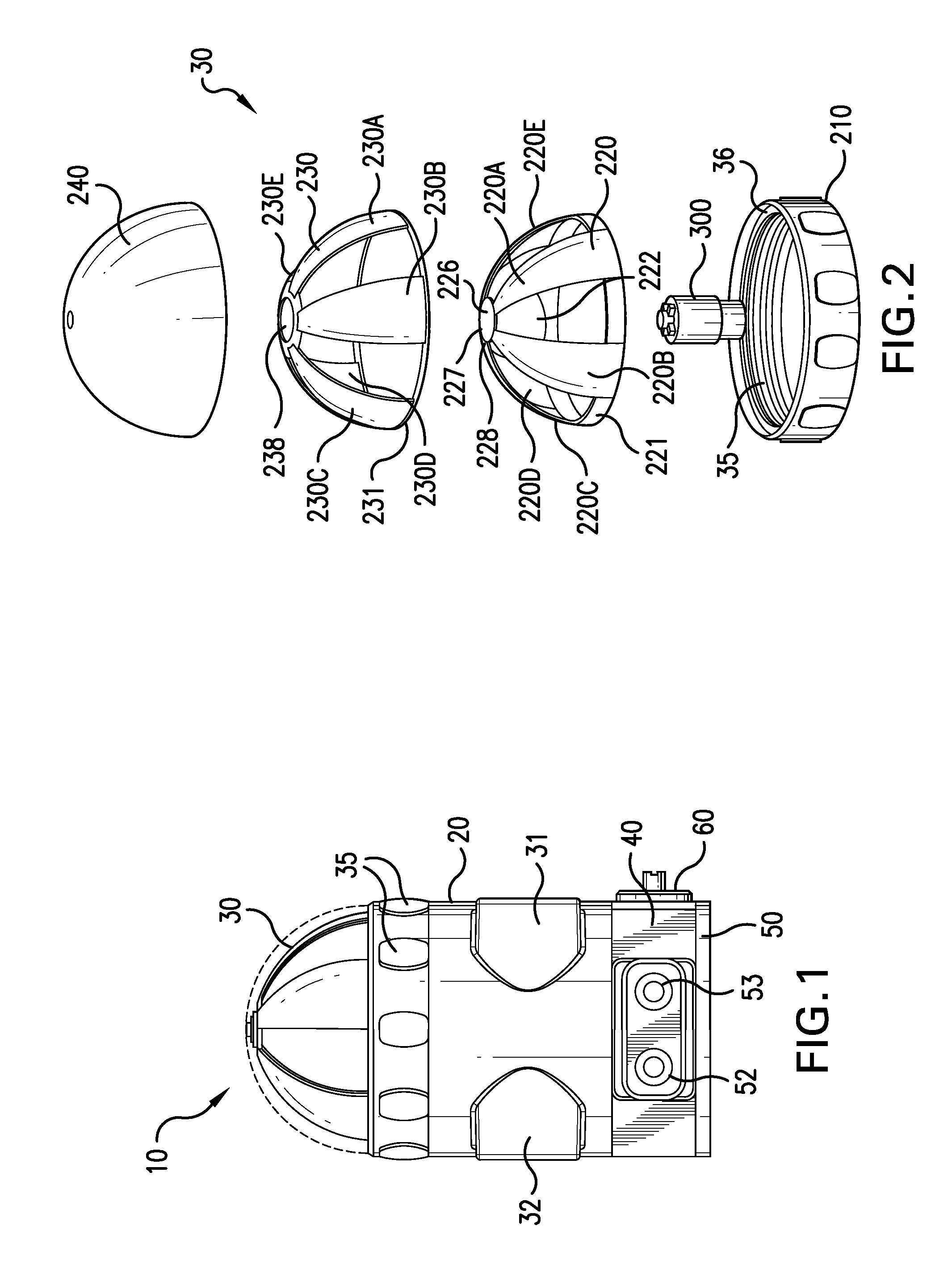
[0015]FIG. 1 illustrates an exemplary embodiment of a valve controller 10 to be mounted on a valve or pneumatic valve actuator (not shown). Controller 10 includes trigger enclosure or housing 20, beacon assembly 30, manifold 40 and mounting plate 50. Housing 20 is cylindrical in shape and beacon assembly 30 includes circumferential indentations 35 for gripping purposes and first and second electrical conduit ports 31 and 32 to provide electrical supply to and from controller 10. Ports 31 and 32 can be adapted to connect to, for example, ½″ NPT or like conduit. The beacon assembly 30 and manifold 40 define an enclosure in which all for mechanical and electronic components are housed to avoid exposure to operative conditions.

[0016]FIG. 2 illustrates a perspective view of beacon assembly 30 to indicate the position or operating state of a valve controlled by controller 10. For example, beacon assembly 30 may provide a distinct visual signal for a process valve operating under normal co...


PUM


Abstract

A controller for controlling a valve is disclosed including a manifold assembly, a valve position indicator and a trigger assembly. An operating media distribution system is disposed in the manifold assembly and an electronic control unit is disposed in the controller. The electronic control unit operates at least one electromagnetic valve to control operating media flow via the operating media distribution system to activate an actuator which opens or closes the valve. The trigger assembly includes a cylinder adapted to receive an actuator shaft and provide a self setting mechanism corresponding to the stroke length of the actuator shaft.

Description

FIELD OF THE INVENTION[0001]The present invention relates generally to valve controllers, and further to an integrated valve controller for use with diaphragm valves and associated actuators. The present invention also relates to a visual indicator providing signals indicative of the position of a valve and to a self setting method associated with the controller.BACKGROUND OF THE INVENTION[0002]Different types of process valves are employed for different purposes. For example, a diaphragm valve may be used in the chemical, pharmaceutical and food industries. A valve controller is employed to control the position of a valve based on pneumatic pressure and may also provide a visual indication of such position. These visual indicators sometimes extend above the plane of the controller (e.g. pop-up indicators), thereby increasing the space required to operate the controller. Typically, many hundreds and sometimes thousands of valves are used in a processing plant where each of these val...

Claims


Application Information

Patent Timeline
Patent Type & Authority Applications(United States)
IPC IPC(8): F15B13/043
CPCF16K37/0058F16K37/0008F15B5/006F16K31/12F16K37/0033Y10T137/8275Y10T137/8359Y10T137/86614
Inventor MINERVINI, LEOJORDAN, ERICENDRES, ROBERT J.
Owner WESTLOCK CONTROLS
Why Eureka
Try Eureka