
Technique for improving ion implantation based on ion beam angle-related information

a technology of angle-related information and ion beam, which is applied in the field of ion implantation, can solve the problems of exacerbated problem, asymmetrical dopant profile may not be acceptable, angle errors may be measured with respect,

Active Publication Date: 2008-04-03
VARIAN SEMICON EQUIP ASSOC INC
View PDF10 Cites 15 Cited by
  • Summary
  • Abstract
  • Description
  • Claims
  • Application Information

AI Technical Summary

Benefits of technology

[0026]In accordance with further aspects of this particular exemplary embodiment, the method may further comprise calculating, based on the ion beam angle distribution for the one or more potential scanning modes and a substrate topography, a

Problems solved by technology

Any small error in the average incident angle may further exacerbate this problem.
However, in general, such angle errors may be measured with respect to any predetermined angle.
For certain applications, such an asymmetrical dopant profile may not be acceptable.
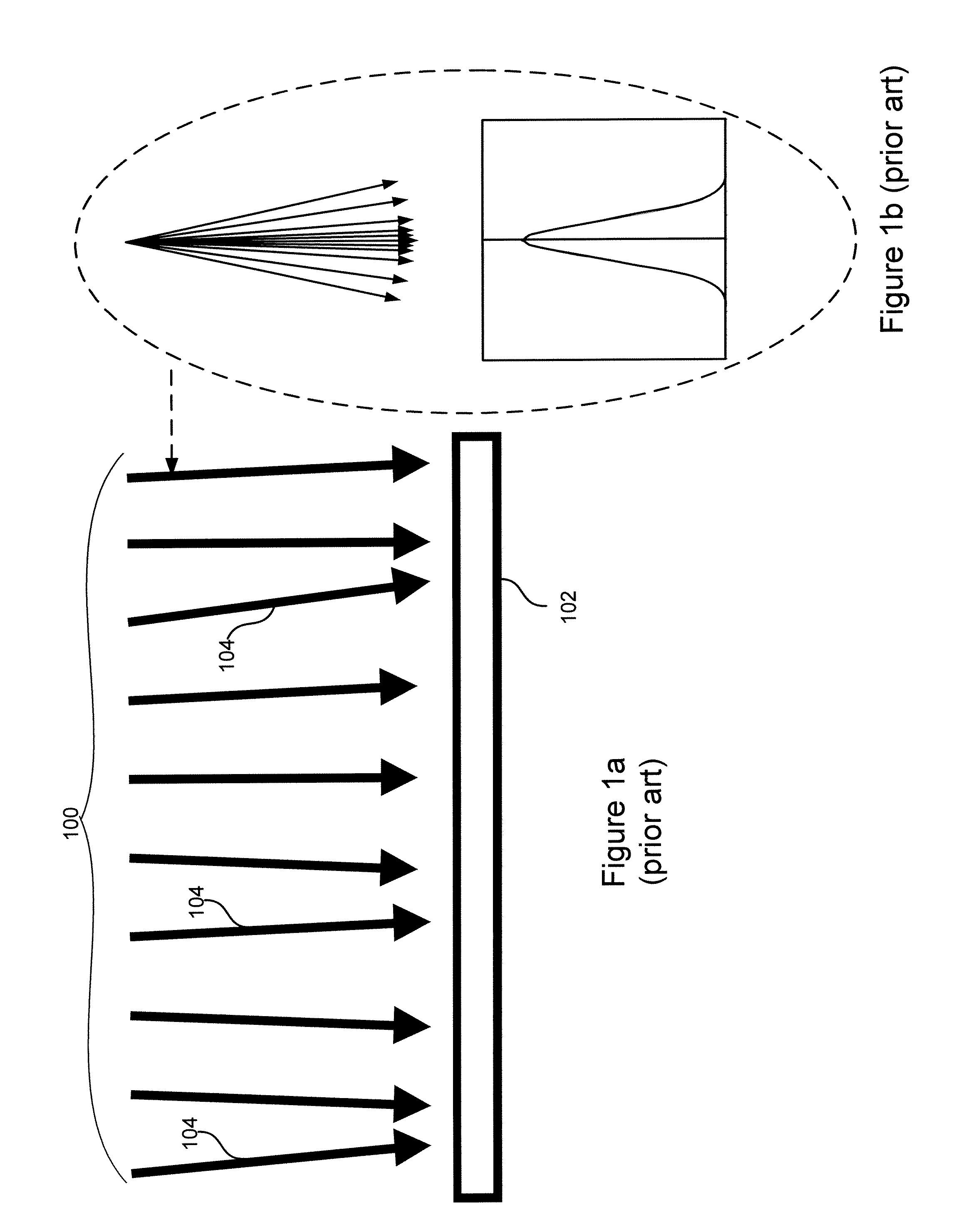
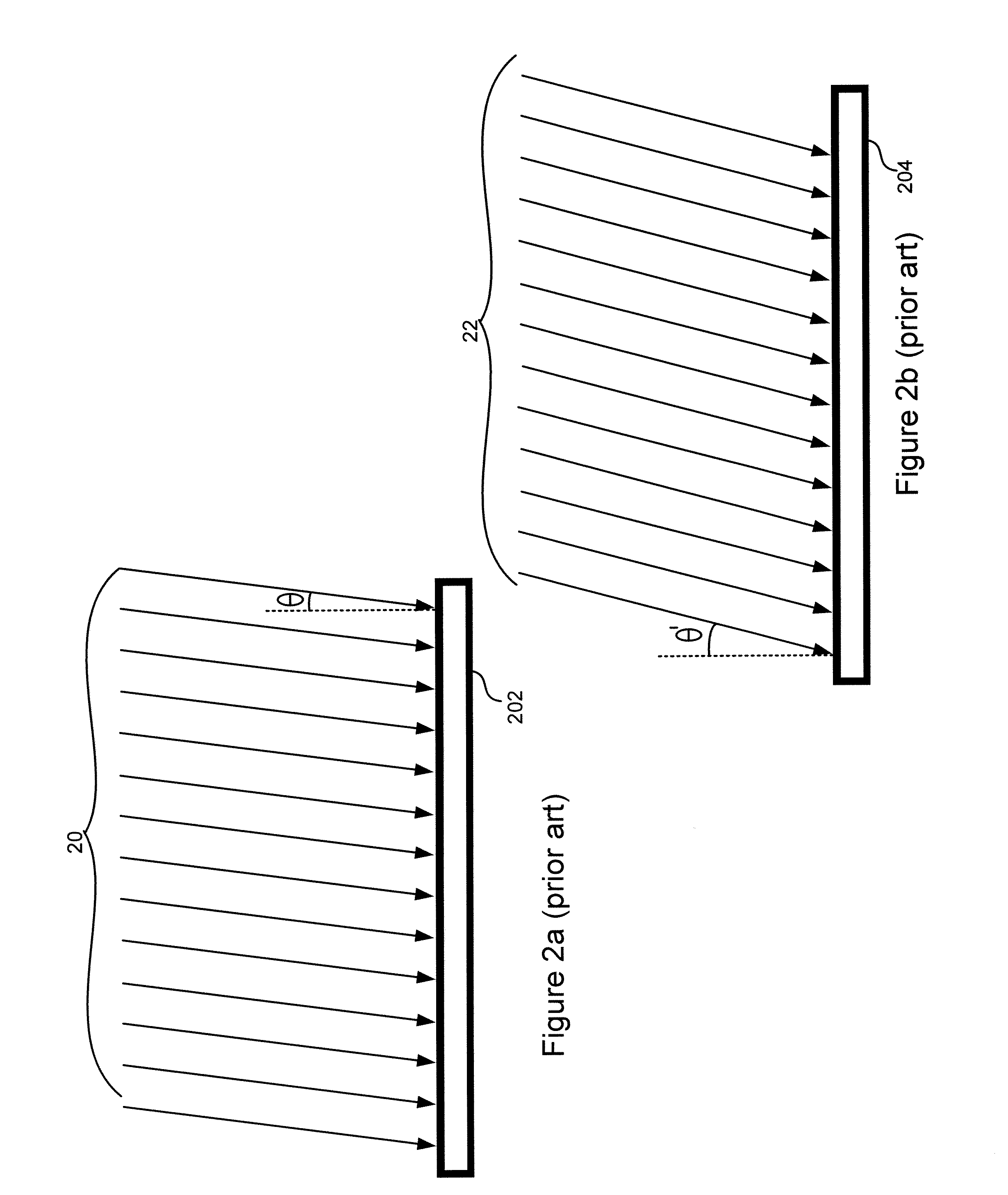
If the ion beam incident angles and / or angle spread are not properly controlled in the implantation and doping processes, the above-described angle variations may cause device performance variations and even yield problems, as illustrated in FIGS. 5a and 5b. FIG. 5a depicts an ion beam 50 with zero angle error and a small angle spread.
In an extreme case as for high aspect ratio structures, the asymmetry in the dose distributions may cause the device to be inoperable.
As the device feature size continues to shrink, the device-level, wafer-level, and wafer-to-wafer angle variations, if left uncontrolled, may cause more performance variations and other detrimental effects.
The setup-to-setup variations in ion beam angle distributions may also cause process repeatability problems in an ion implanter system.
In extreme cases, the ion beam angle variations may lead to yield losses.
As described above, uncontrolled ion beam incident angles and angle spread may cause significant performance variations among different wafers processed in the same implanter.
Existing methods for setting up an ion implanter system have typically been limited to the repeatability of implant doses.
No known method manages to effectively control or minimize dose skews and / or angle skews over an entire wafer and / or among different wafers.

Method used


Image

  • Technique for improving ion implantation based on ion beam angle-related information
  • Technique for improving ion implantation based on ion beam angle-related information
  • Technique for improving ion implantation based on ion beam angle-related information

Examples


Embodiment Construction

[0042]Embodiments of the present disclosure are directed to a technique for improving ion implantation, wherein angle-related information associated with an ion beam is used as an input to predict performance metric resulting from one or more scanning modes. Based on the prediction, a desired scanning mode that results in a desired effective angle distribution across the wafer may be selected for an ion implantation production.

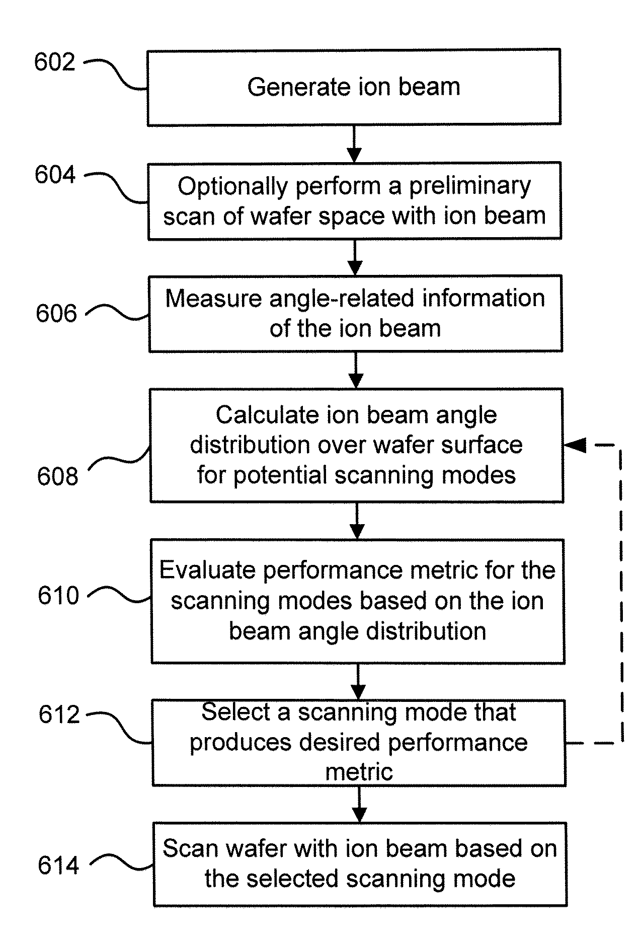
[0043]Referring to FIG. 6, there is shown a flowchart illustrating an exemplary method for improving ion implantation based on ion beam angle-related information in accordance with an embodiment of the present disclosure.

[0044]In step 602, an ion beam may be generated in an ion implanter. The ion beam may be, for example, a ribbon beam or a spot beam. No matter what shape of cross section the ion beam has, the method for controlling its angle distribution as described below may be substantially the same. The generated ion beam may be set up (e.g., tuned and sh...


PUM


Abstract

A technique for improving ion implantation based on ion beam angle-related information is disclosed. In one particular exemplary embodiment, the technique may be realized as a method for improving ion implantation. The method may comprise obtaining angle-related information associated with an ion beam. The method may also comprise calculating, based on the angle-related information, an ion beam angle distribution over a wafer for one or more potential scanning modes. The method may further comprise selecting a desired scanning mode from the one or more potential scanning modes based on an evaluation of performance metric caused by the ion beam angle distribution.

Description

FIELD OF THE DISCLOSURE[0001]The present disclosure relates generally to ion implantation and, more particularly, to a technique for improving ion implantation based on ion beam angle-related information.BACKGROUND OF THE DISCLOSURE[0002]Ion implantation is a process of depositing chemical species into a substrate by direct bombardment of the substrate with energized ions. In semiconductor fabrication, ion implanters are used primarily for doping processes that alter the type and level of conductivity of target materials. A precise doping profile in an integrated circuit (IC) substrate is often crucial for proper IC performance. To achieve a desired doping profile, one or more ion species may be implanted in different doses, at different energies and different incident angles.[0003]Traditionally, an ion implant process in semiconductor manufacturing is followed by a thermal annealing step to activate implanted dopant atoms. This thermal annealing step controls the spread of dopant a...

Claims


Application Information

Patent Timeline
IPC IPC(8): H01J37/304H01J37/317
CPCH01J37/304H01J37/3171H01J2237/1501H01J2237/31703H01J2237/3045H01J2237/30483H01J2237/24528
Inventor GUPTA, ATULENGLAND, JONATHAN GERALD
Owner VARIAN SEMICON EQUIP ASSOC INC
Learn More