Remote control unit for a programmable multimedia controller

a multimedia controller and remote control technology, applied in the field of device control, can solve the problems of difficult use, non-intuitive control schemes, and complex controls to manipulate and select, and achieve the effect of facilitating detailed control without bulky input devices

Active Publication Date: 2008-04-03
SAVANT SYST INC
View PDF16 Cites 106 Cited by
  • Summary
  • Abstract
  • Description
  • Claims
  • Application Information

AI Technical Summary

Benefits of technology

[0017]A remote control unit is provided for operating a programmable multimedia controller, the remote control unit including an annular touch sensor for manipulating an annular menuing system displayed on a display device. In one embodiment, the annular menuing system includes a number of selectable options displayed as text or graphic icons. In response to a user gesturing by scrolling clockwise or counter-clockwise about the annular touch sensor, pressing firmly on the annular touch sensor, or tapping at a particular location on the annular touch sensor, the selectable options rotate in the annular menuing system. A user may fully direct their visual attention to the annular menuing system, as the remote control unit may be manipulated from tactile sensation. When an option is brought to a designated position in the menuing system, it is selected by a further action of the user. In a second embodiment, the annular menuing system includes a number of regions displayed in an annular manner, and a selection cursor is disposed upon the menuing system. In response to a user gesturing on the annular touch sensor by scrolling clockwise or counter-clockwise, the selection cursor is moved in that direction on the annular menuing system. Alternately, by pressing firmly or tapping at a particular location on the annular touch sensor, a region located at a corresponding location of the annular menuing system is selected. By selection of selectable options or regions, corresponding numerals, characters, text, devices, commands, Internet web pages, menus, or other options may be chosen. In this manner, the combination of the annular menuing system and the remote control unit with the annual sensor may replicate many of the functions provided by a mouse and keyboard, facilitating detailed control absent bulky input devices.

Problems solved by technology

While once electronic devices could adequately be controlled with only a handful of analog knobs and switches, modern electronic devices often present users with a vast array of configurable options and parameters, which require complex controls to manipulate and select.
Yet actual convenience is seldom achieved with conventional remote control units.
Users are typically burdened with having to manipulate a number of separate, device-specific remote control units, each of which typically implements a different control scheme.
Many of the control schemes commonly employed with remote control units are non-intuitive and difficult to use.
The crowded button layout of button-centric remote control units often makes it difficult to select a desired button from the many buttons available, especially in low-light conditions.
If a user inadvertently presses the “wrong” button, a device may perform an unwanted action or enter an undesired mode or state.
This may confuse or aggravate the user.
Further, sometimes a user may be uncertain which button to press in order to activate a desired function.
In short, many button-centric remote control units are far from intuitive and easy-to-use.
Furthermore, while a variety of so-called “universal” remote control units exist that claim to improve upon the shortcomings of device-specific remote control units, conventional “universal” remote controls generally fall far short of their claims.
So, while the control schemes of the device specific remote control units are all implemented on a single remote control unit, they are not unified or simplified in any way.
Further, since conventional “universal” remote control units attempt to control a range of devices, they typically have even more buttons with cryptic legends than device-specific remote controls.
Also, most “universal” remote control units tend to be far from universal, as they typically do not operate with devices other than audio and video devices.
For example, conventional “universal” remote controls do not generally include functionality for controlling telephony devices, data devices, security devices, motor-operated devices, relay-operated devices, Internet access / browser devices, general-purpose computers, handicap assistance devices, and / or other types of devices.
These touch-panel controllers incorporate central processor units, graphics controllers, I / O interfaces and other complex components similar to those found in portable computers, rendering them complicated and costly to manufacture.
Further, such touch-screen controllers generally require extensive custom programming to adapt to particular installations.
Thus, their complexity and cost renders them unsuitable for many applications.
Furthermore, high-end touch-panel controllers, conventional “universal” remote control units, and device specific remote control units typically lack any type of location-awareness, i.e. the ability to incorporate knowledge of the remote control unit's current location into the control scheme, or user-awareness, i.e. the ability to incorporate knowledge of the remote control unit's current user into the control scheme.
This burdens the user, requiring the user to make making all location dependent decisions themselves and forgo the convenience of user-dependent control.
Thus, a simple action may become quite daunting, and require trial and error to execute.
As the number of devices controlled by a remote control unit grows, the difficulties caused by a lack of location-awareness become even more apparent.
As is apparent, this would be quite burdensome to do each time one desires to turn on a light, and much of the convenience of remotely controlled lighting is lost.
A user who desires to have his or her own personal control scheme is not accommodated.

Method used


Image

  • Remote control unit for a programmable multimedia controller
  • Remote control unit for a programmable multimedia controller
  • Remote control unit for a programmable multimedia controller

Examples


Embodiment Construction

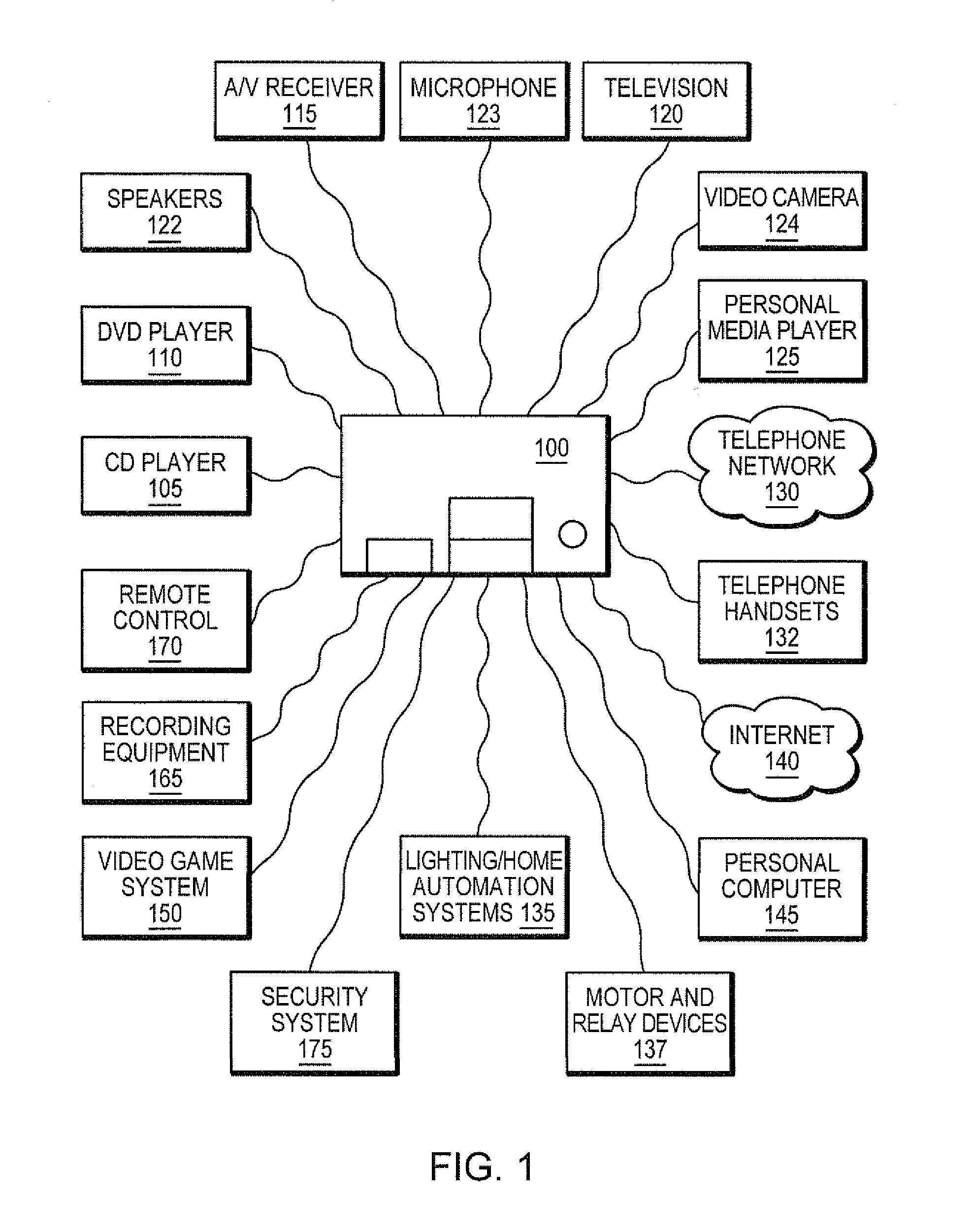
[0030]FIG. 1 is a block diagram of an illustrative programmable multimedia controller 100, interconnected to a number of devices, which may be used in conjunction with the remote control unit disclosed herein. The term “programmable multimedia controller” should be interpreted broadly as a device capable of controlling, switching data between, and / or otherwise interoperating with, a variety of electronic devices, such as audio devices, video devices, telephony devices, data devices, security devices, motor-operated devices, relay-operated devices, Internet access / browser devices, general-purpose computers, handicap assistance devices, and / or other types of devices. A programmable multimedia controller may be configured to perform all these functions and work with all these devices, or to perform a selected subset of functions and operate with a selected subset of devices.

[0031]In the example of FIG. 1, the programmable multimedia controller 100 is connected to a wide range of audio / ...


PUM


Abstract

A remote control unit is provided that includes an annular touch sensor for manipulating an annular menuing system displayed on a display device. In response to a user gesturing by scrolling clockwise or counter-clockwise about the annular touch sensor, pressing firmly on the annular touch sensor, or tapping at a particular location on the annular touch sensor, the annular menuing system is manipulated to select particular items. The remote control unit is further configured to implement location-awareness features. Control is adapted to the location of the remote control unit and to the devices located nearby to this location. Similarly the remote control unit is further configured to implement user-awareness features, such that the control is adapted for the individual preferences of different users.

Description

RELATED CASES[0001]This application is related to the following United States Patent Applications:[0002]Ser. No. 11 / 314,112 entitled, MULTIMEDIA CONTROLLER WITH PROGRAMMABLE SERVICES, by Robert P. Madonna, et al., and[0003]Ser. No. 11 / 314,664 entitled SYSTEM AND METHOD FOR A PROGRAMMABLE MULTIMEDIA CONTROLLER, by Robert P. Madonna, et al, the teachings of both of which are expressly incorporated by reference.BACKGROUND OF THE DISCLOSURE[0004]1. Field of the Disclosure[0005]The present disclosure relates generally to device control, and more particularly to a remote control unit for a programmable multimedia controller that controls a variety of electronic devices, such as audio devices, video devices, telephony devices, data devices, security devices, motor-operated devices, relay-operated devices, Internet access / browser devices, general-purpose computers, handicap assistance devices, and / or other types of devices.[0006]2. Background Information[0007]With the ever increasing comple...

Claims


Application Information

Patent Timeline
Patent Type & Authority Applications(United States)
IPC IPC(8): G08C19/00H04W4/80H04N5/00H04W4/02H04W4/029
CPCG01S5/02H04W4/02G08C17/02G08C2201/30G08C2201/91G08C2201/92H04N5/4403H04N2005/4416H04N2005/4428H04N2005/4444G06F3/0488H04N21/42222H04N21/4312H04N21/42225H04N21/47G05B15/02H04W4/008G01S19/14H04W4/80H04N21/42212H04N21/42206H04N21/4532H04N21/42204G01S5/013H04N5/445H04N21/42226H04W4/029
Inventor MADONNA, ROBERT P.NOONAN, MICHAEL E.SILVA, MICHAEL C.CORSINI, PETER H.JACOBSON, ARTHUR A.
Owner SAVANT SYST INC
Why Eureka
Try Eureka