Method for Improving Thermal Conductivity in Micro-Fluid Ejection Heads

Inactive Publication Date: 2008-04-03
LEXMARK INT INC
View PDF21 Cites 29 Cited by
  • Summary
  • Abstract
  • Description
  • Claims
  • Application Information

AI Technical Summary

Benefits of technology

[0007]One such head has a substrate with a thermal conductivity ranging from about 1.4 W/m-° C. to about 148 W/m-° C., a fluid ejection actuator, and a thermal bus thermally adjacent to the substrate and configured to dissipat

Problems solved by technology

However, the use of silicon substrates has proved unsuitable in achieving micro-fluid ejection heads, such as ink jet devices, having a relatively wide swath ejection head.
This is due to the fragility of such substrates, especially as their dimensions are increased.
Meanwhile, alumina is not traditionally used in thermal micro-fluid ejection heads because of a need for very smooth substrate surfaces (which are required for thin-film processing and correct heating element characteristics).

Method used


Image

  • Method for Improving Thermal Conductivity in Micro-Fluid Ejection Heads
  • Method for Improving Thermal Conductivity in Micro-Fluid Ejection Heads
  • Method for Improving Thermal Conductivity in Micro-Fluid Ejection Heads

Examples


Example

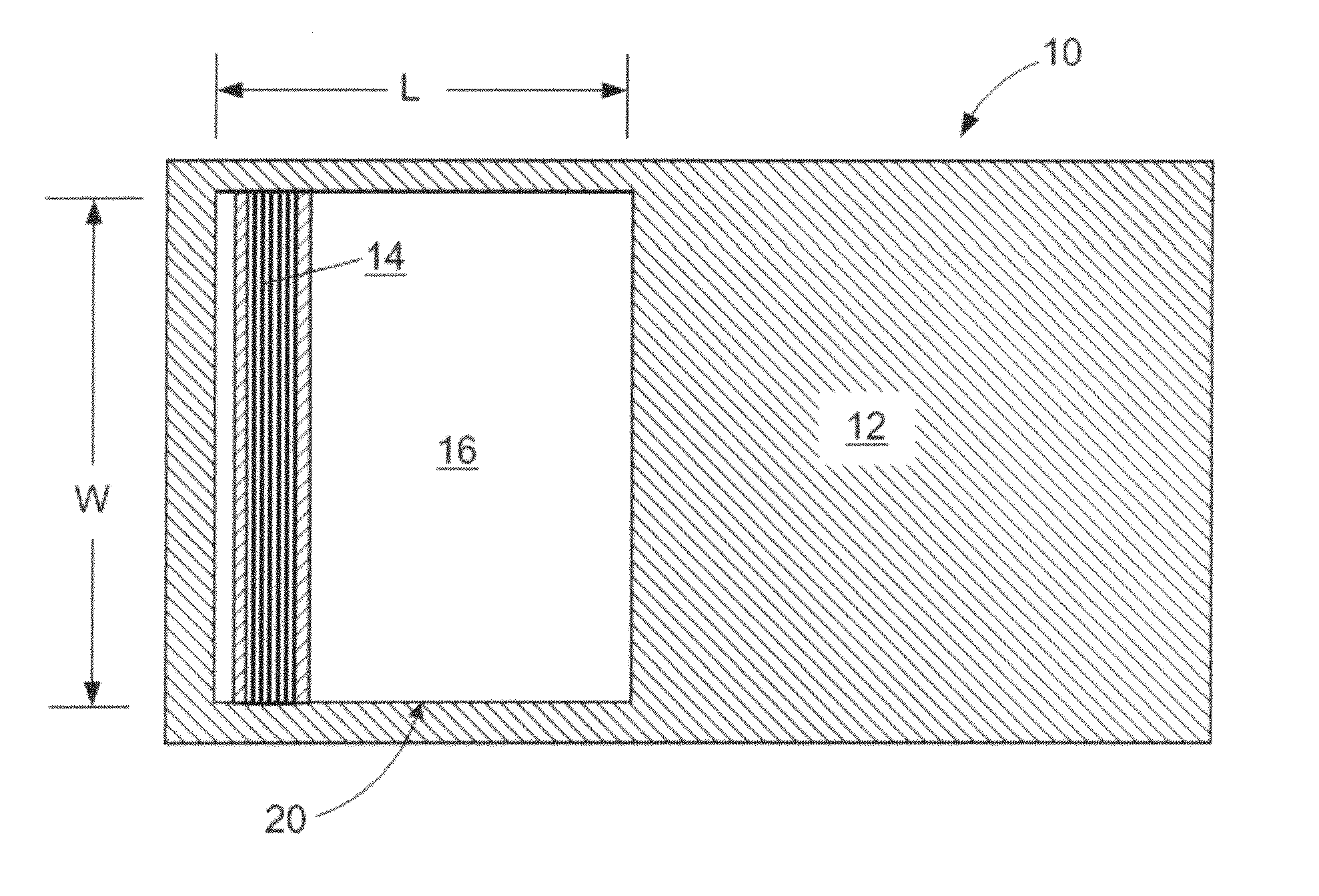
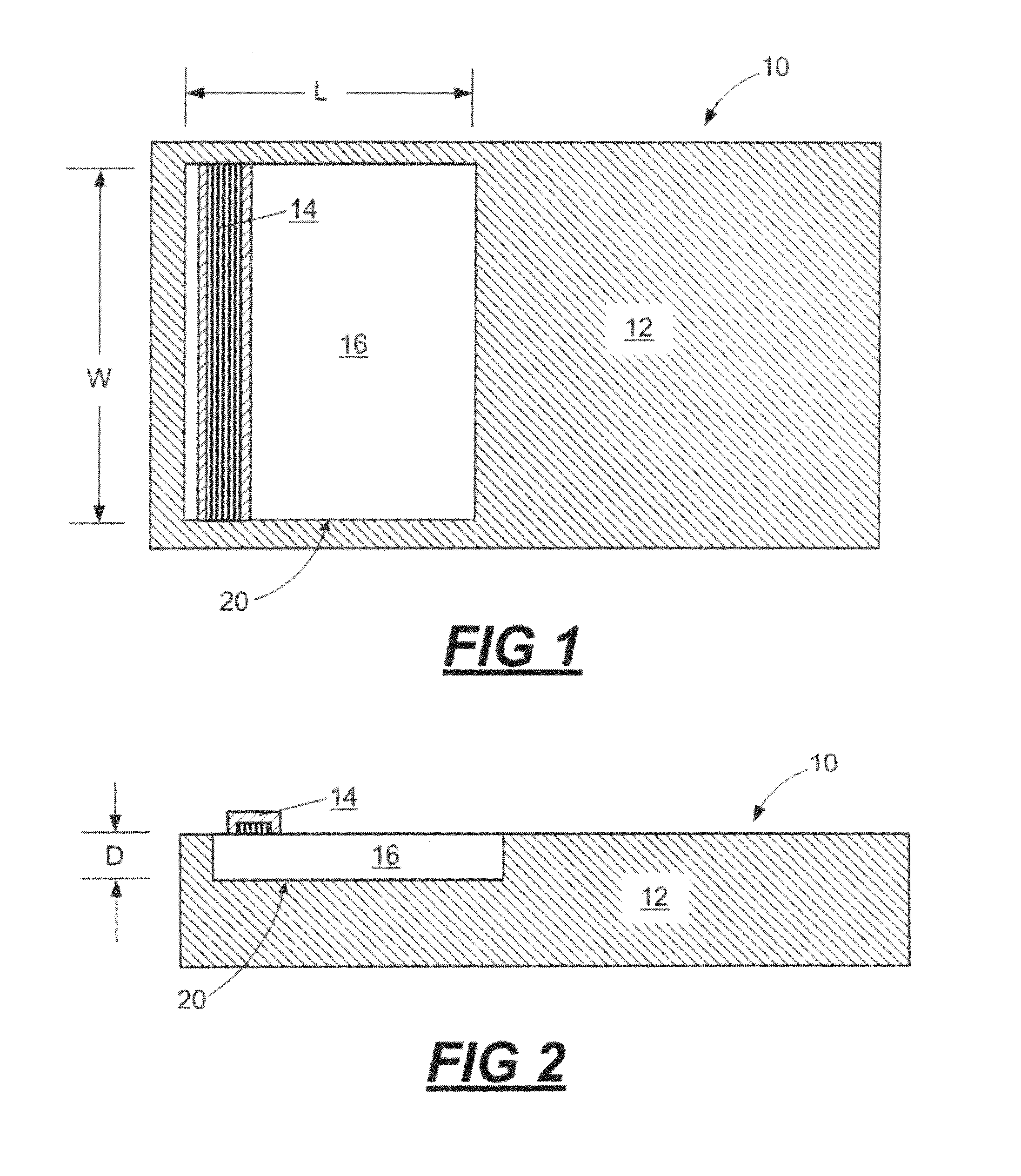
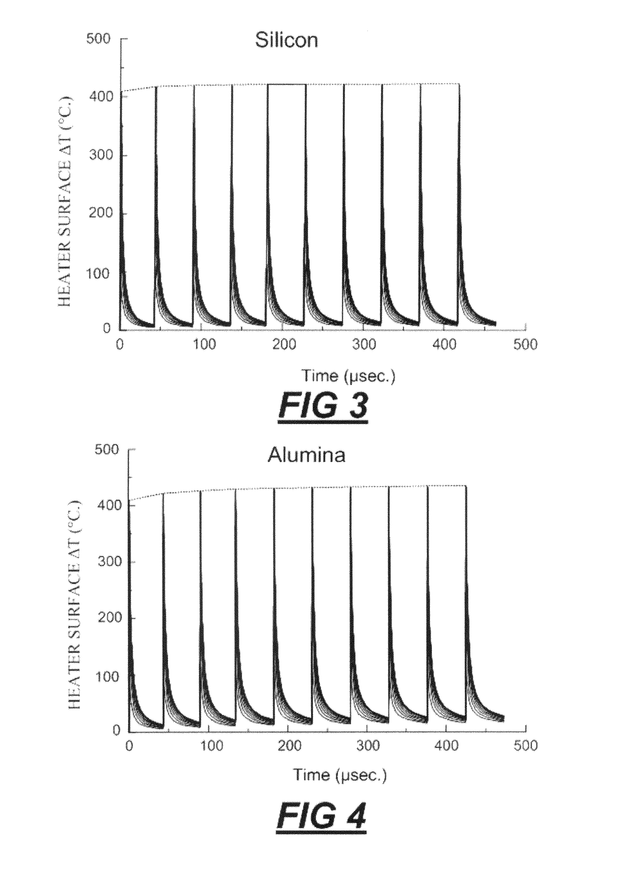
[0020]According to exemplary embodiments disclosed herein, there is provided methods for modifying low thermal conductivity substrates to yield substrates having improved thermal conductivity properties. With reference to FIG. 1, there is shown a plan view of a portion of a micro-fluid ejection head 10, such as an inkjet printhead, having a substrate 12 modified according to such an exemplary embodiment.

[0021]In a manner well known in the art, thermal fluid ejection actuators, such as heater resistors, are formed adjacent to a device surface of the modified substrate 12 in an actuator region 14 of the substrate 12. Upon activation of a thermal fluid ejection actuator in the actuator region 14, fluid supplied through a fluid path(s) in an associated fluid reservoir and corresponding fluid flow slot(s) in the substrate 12 is caused to be ejected toward a media through a nozzle in a nozzle plate associated with the substrate 12.

[0022]Substrate 12 represents a base substrate material wh...


PUM


Abstract

Methods for improving the thermal conductivity of a substrate for a micro-fluid ejection head and micro-fluid ejection heads are provided. One such head includes a substrate having a thermal conductivity ranging from about 1.4 W/m-° C. to about 148 W/m-° C., a fluid ejection actuator, and a thermal bus thermally adjacent to the substrate and configured to dissipate heat associated with the operation of the actuator. Exemplary modified substrates have improved thermal conductivity characteristics as compared to a corresponding substrate not modified to include the thermal bus.

Description

FIELD OF THE DISCLOSURE[0001]The present disclosure is generally directed toward methods for improving the thermal conductivity of micro-fluid ejection heads. More particularly, in an exemplary embodiment, the disclosure relates to improvements in the manufacture of micro-fluid ejection heads utilizing alternative substrate materials.BACKGROUND AND SUMMARY[0002]Multi-layer circuit devices such as those used in the manufacture of micro-fluid ejection heads have a plurality of electrically conductive layers separated by insulating dielectric layers and applied adjacent to a substrate. Thermal energy generators or heating elements, usually resistors, are located on a surface of the substrate to heat and vaporize the fluid to be ejected.[0003]Conventionally, the substrate material has been made substantially of alumina (in the case of devices utilizing silicon chip attachments) or silicon (in the case of traditional thermal micro-fluid ejection heads), typically circular single crystall...

Claims


Application Information

Patent Timeline
IPC IPC(8): B41J2/06
CPCB41J2/14129B41J2/1408
Inventor CORNELL, ROBERT LEECORNELL, ROBERT WILSONDROEGE, CURTIS RAYKLEMO, ELIOSSTRUNK, TIMOTHY LOWELLWALDECK, MELISSA MARIE
Owner LEXMARK INT INC
Why Eureka
Try Eureka