EMI protection housing and connector seal for circuit packs installed in electronics systems

a technology for electronics systems and connector seals, which is applied in the direction of electrical apparatus construction details, support structure mounting, rack/frame construction, etc., can solve the problems of reducing the service life of the circuit pack, so as to reduce the size of the telecommunications base station cabinet. , the effect of preventing corrosion

Inactive Publication Date: 2008-04-03
LUCENT TECH INC
View PDF5 Cites 24 Cited by
  • Summary
  • Abstract
  • Description
  • Claims
  • Application Information

AI Technical Summary

Benefits of technology

[0003]The present invention provides a novel housing for circuit packs which may, for example, be inserted into an electronics system such as, for example, a telecommunications base station cabinet. In accordance with an illustrative embodiment of the present invention, a circuit pack housing having a single piece plastic design surrounds a circuit pack and advantageously provides EMI protection thereof. In particular, all of the internal walls of this illustrative circuit pack housing are advantageously metalized, and the inner surface of the housing advantageously comprises one or more grounding tabs with metalized surfaces, thereby grounding the circuit pack.
[0004]In accordance with one illustrative embodiment of the present invention, the metalized plastic circuit pack housing also advantageously comprises two opposing living hinges and a self latching mechanism, such that when the circuit pack is placed inside the housing and the housing is closed on itself (i.e., with use of the living...

Problems solved by technology

Existing designs for electronics systems such as telecommunications base station cabinets are typically quite bulky because, inter alia, it is necessary that sufficient space exists between the various circuit packs installed therein.
This necessarily results in either a limitation on the number of circuit packs...

Method used


Image

  • EMI protection housing and connector seal for circuit packs installed in electronics systems
  • EMI protection housing and connector seal for circuit packs installed in electronics systems
  • EMI protection housing and connector seal for circuit packs installed in electronics systems

Examples


Embodiment Construction

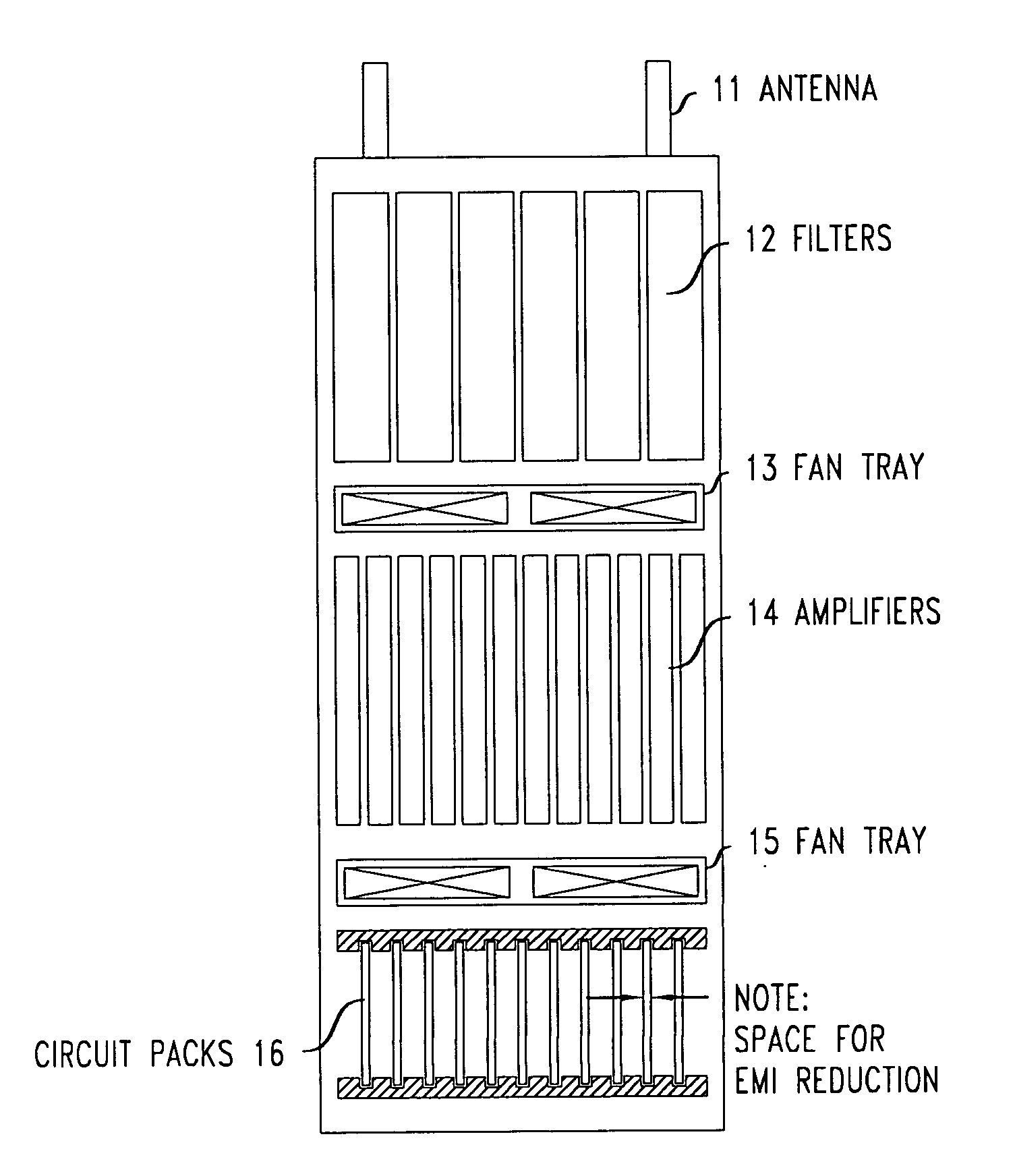
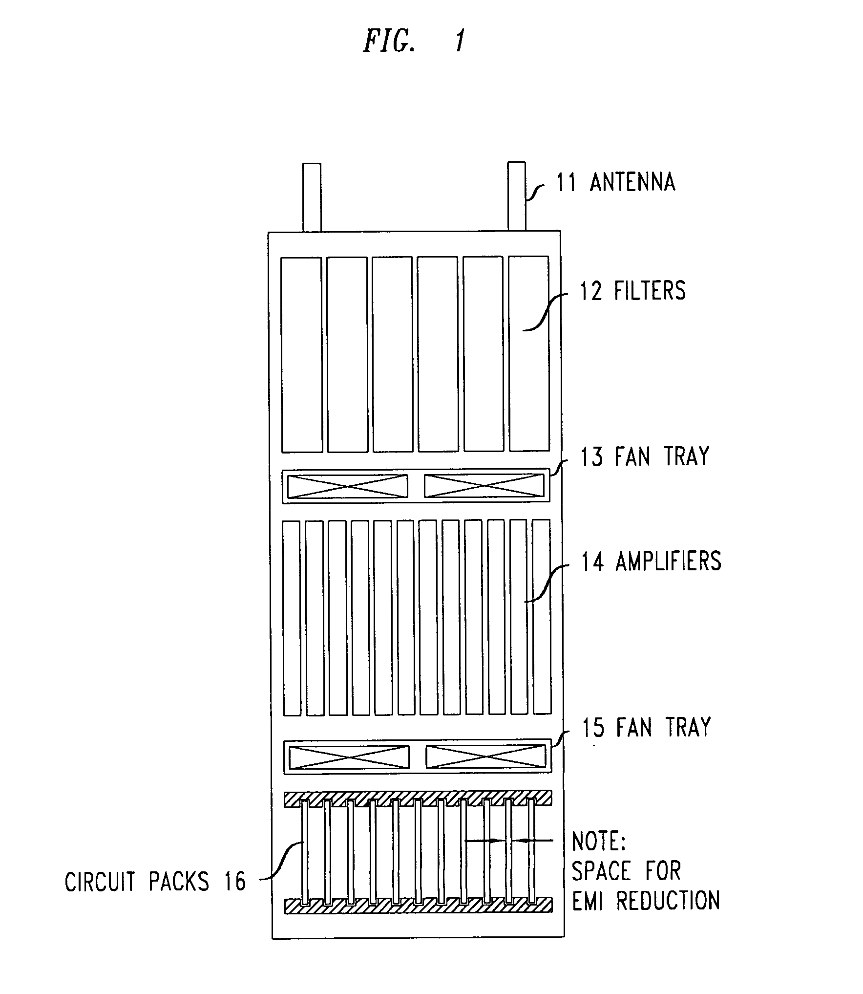
[0011]FIG. 1 shows a front view of a prior art telecommunications base station electronics system. The prior art system of FIG. 1 includes a number of component sections (i.e., shelves), and comprises antennae 11 (two are shown), a shelf comprising filters 12, a shelf comprising amplifiers 14, and a shelf comprising circuit packs 16, as well as fan tray 13 (positioned between the shelf comprising filters 12 and the shelf comprising amplifiers 14), and fan tray 15 (positioned between the shelf comprising amplifiers 14 and the shelf comprising circuit packs 16).

[0012]As can be seen in the figure, circuit packs 16 may be installed in their corresponding shelf with use of slotted openings in the top and bottom portions of the shelf, thus allowing the circuit packs to be slid into place. Also, as is typical, the back sides of many of the included components may be connected to either a cabling harness or, preferably, a PWB (Printed Wiring Board) backplane (which is not visible in the fig...


PUM


Abstract

A circuit pack housing for providing EMI protection for a circuit pack which may be inserted into an electronics system such as a telecommunications base station cabinet. The circuit pack housing has a single piece plastic design which surrounds the enclosed circuit pack. The internal walls of the circuit pack housing are metalized, and the inner surface of the housing comprises one or more grounding tabs with metalized surfaces. The metalized plastic circuit pack housing also comprises two opposite living hinges and a self latching mechanism, such that when the circuit pack is placed inside the housing and the housing is closed on itself (i.e., with use of the living hinges), the circuit pack is sealed within the housing and protected from EMI thereby. Moreover, the housing may include protruding flexible tabs at the ends thereof, which advantageously seals around the connector which energizes the circuit pack.

Description

FIELD OF THE INVENTION[0001]The present invention relates generally to the field of electronics system enclosures such as, for example, telecommunications base station cabinets, and more particularly to a housing for circuit packs installed in such systems.BACKGROUND OF THE INVENTION[0002]Existing designs for electronics systems such as telecommunications base station cabinets are typically quite bulky because, inter alia, it is necessary that sufficient space exists between the various circuit packs installed therein. In particular, and as is well known to those of ordinary skill in the art, such spacing is needed to provide for EMI (Electromagnetic Interference) protection between nearby circuit packs. This necessarily results in either a limitation on the number of circuit packs that can be installed in a given electronics system and / or an undesirable increase in the size and bulkiness of the system. One alternative approach to the design of electronics systems such as telecommun...

Claims


Application Information

Patent Timeline
IPC IPC(8): H05K9/00H05K7/18H05K7/14
CPCH05K9/0062H04Q1/155H04Q1/025H04Q1/116
Inventor CROCKER, MICHAEL A.DAOUD, BASSEL H.HOLIHAN, LOREN J.SCHWORK, THOMAS JOSEPHWIESE, CHRISTOPHER K.
Owner LUCENT TECH INC
Why Eureka
Try Eureka