
Fluid mixer, fluid mixing apparatus, and nozzle member

a fluid mixing apparatus and mixer technology, applied in the direction of mixing, chemistry apparatus and processes, mixers, etc., can solve the problems of reducing the distance between the leading end portion of the nozzle and the mixing portion, reducing the mixing efficiency, etc., to enhance the efficiencies of treating (mixing), and enhance the efficiencies of fluid mixing apparatus.

Inactive Publication Date: 2008-04-03
ANEMOS
View PDF37 Cites 15 Cited by
  • Summary
  • Abstract
  • Description
  • Claims
  • Application Information

AI Technical Summary

Benefits of technology

[0006] However, the installation of the tubular nozzle in the fluid mixer decreases the distance between the leading end portion of the nozzle and the mixing portion. Accordingly, before the introduction of the fluid into the mixing portion, the extent of mixing or contacting the fluid introduced from the nozzle with another fluid introduced by the negative pressure effect is decreased. Thus, the efficiencies of treatments, such as mix, stir, and contact in the mixing portion may be decreased. Further, since the fluid mixer includes semielliptical blades therein, the flow rate of introducing fluid is limited to approximately 2 m / sec. or less, thereby also decreasing mixing efficiency.
[0007] In view of such consequences as described above, embodiments of the present invention provides a fluid mixer, a fluid mixing apparatus, and a nozzle member capable of increasing the flow rate of a fluid introduced into the fluid mixer to enhance a negative pressure effect while maintaining the treatment efficiency of a mixing portion.
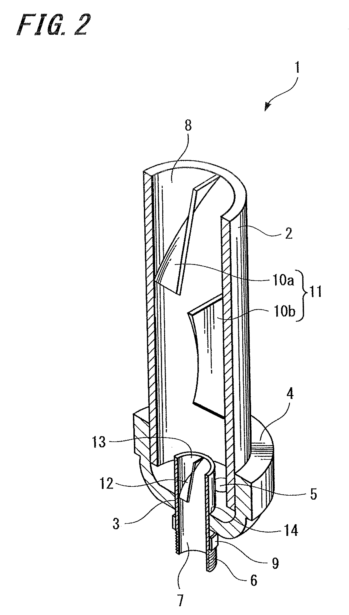
[0021] According to the fluid mixer of an embodiment of the present invention, the blade included in the varying portion causes varied and turbulent streamlines of the fluid flowing through the nozzle member. Consequently, the flow rate of the fluid introduced in the mixer can be maintained in large and facilitate the fluid to be easily mixed with fluids of other types, thereby enhancing the efficiencies of treating (mixing) the fluids in the mixing portion of the fluid mixer.
[0022] According to the embodiment of the present invention, the blade included in the varying portion causes varied and turbulent streamlines of the fluid flowing through the nozzle member. Consequently, the flow rate of the fluid introduced in the mixer can be maintained in large and facilitate the fluid to be easily mixed with fluids of other types, thereby enhancing the efficiencies of treating (mixing) the fluids in the mixing portion of the fluid mixer and enhancing the mixing efficiencies of the fluid mixing apparatus.
[0023] According to the nozzle member of an embodiment of the present invention, the blade included in the varying portion causes varied and turbulent streamlines of the fluid flowing through the inside of the nozzle member. Consequently, the flow rate of the fluid introduced in the mixer can be maintained in large and facilitate the fluid to be easily mixed with fluids of other types, thereby enhancing the efficiencies of treating (mixing) the fluids in the mixing portion of the fluid mixer using the nozzle member. The flow rate of fluid at the mixing portion of the fluid mixer is preferably in a range of approximately 2 m / sec. to 12 m / sec., and more preferably in a range of approximately 3 m / sec. to 8 m / sec.

Problems solved by technology

However, the installation of the tubular nozzle in the fluid mixer decreases the distance between the leading end portion of the nozzle and the mixing portion.
Further, since the fluid mixer includes semielliptical blades therein, the flow rate of introducing fluid is limited to approximately 2 m / sec. or less, thereby also decreasing mixing efficiency.

Method used


Image

  • Fluid mixer, fluid mixing apparatus, and nozzle member
  • Fluid mixer, fluid mixing apparatus, and nozzle member
  • Fluid mixer, fluid mixing apparatus, and nozzle member

Examples


Embodiment Construction

[0037] Hereinafter, fluid mixers in accordance with embodiments of the present invention will be described with reference to attached drawings. However, the present invention is not limited to the following embodiments. Nozzle members in accordance with embodiments of the present invention will also be described with the fluid mixers.

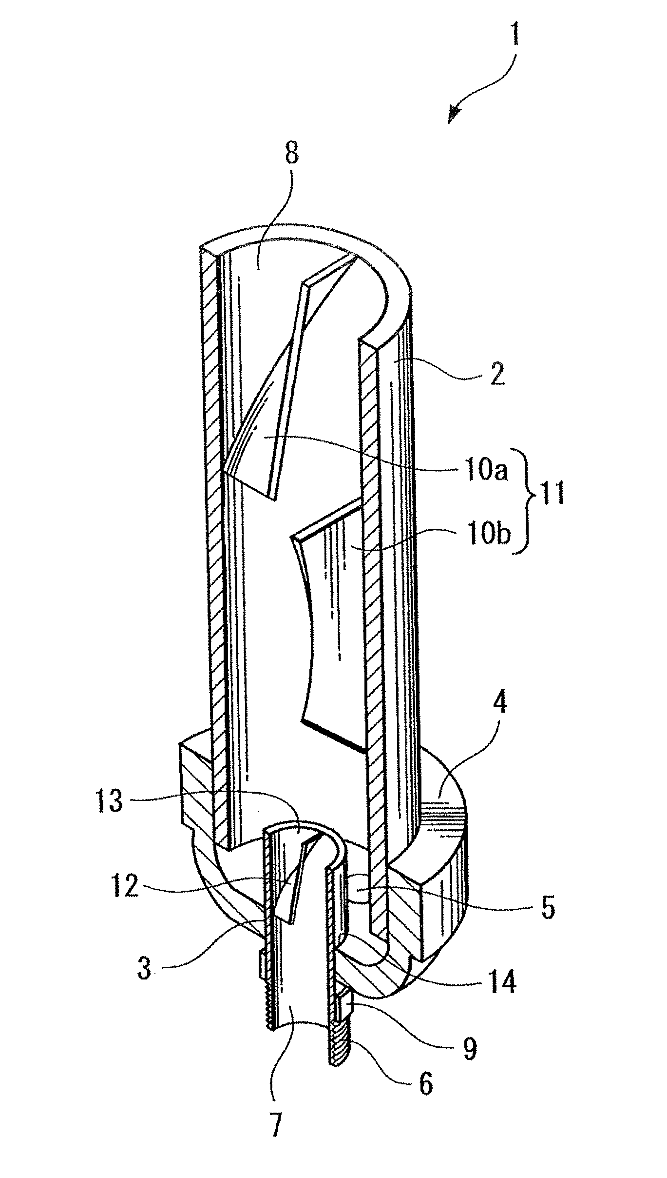
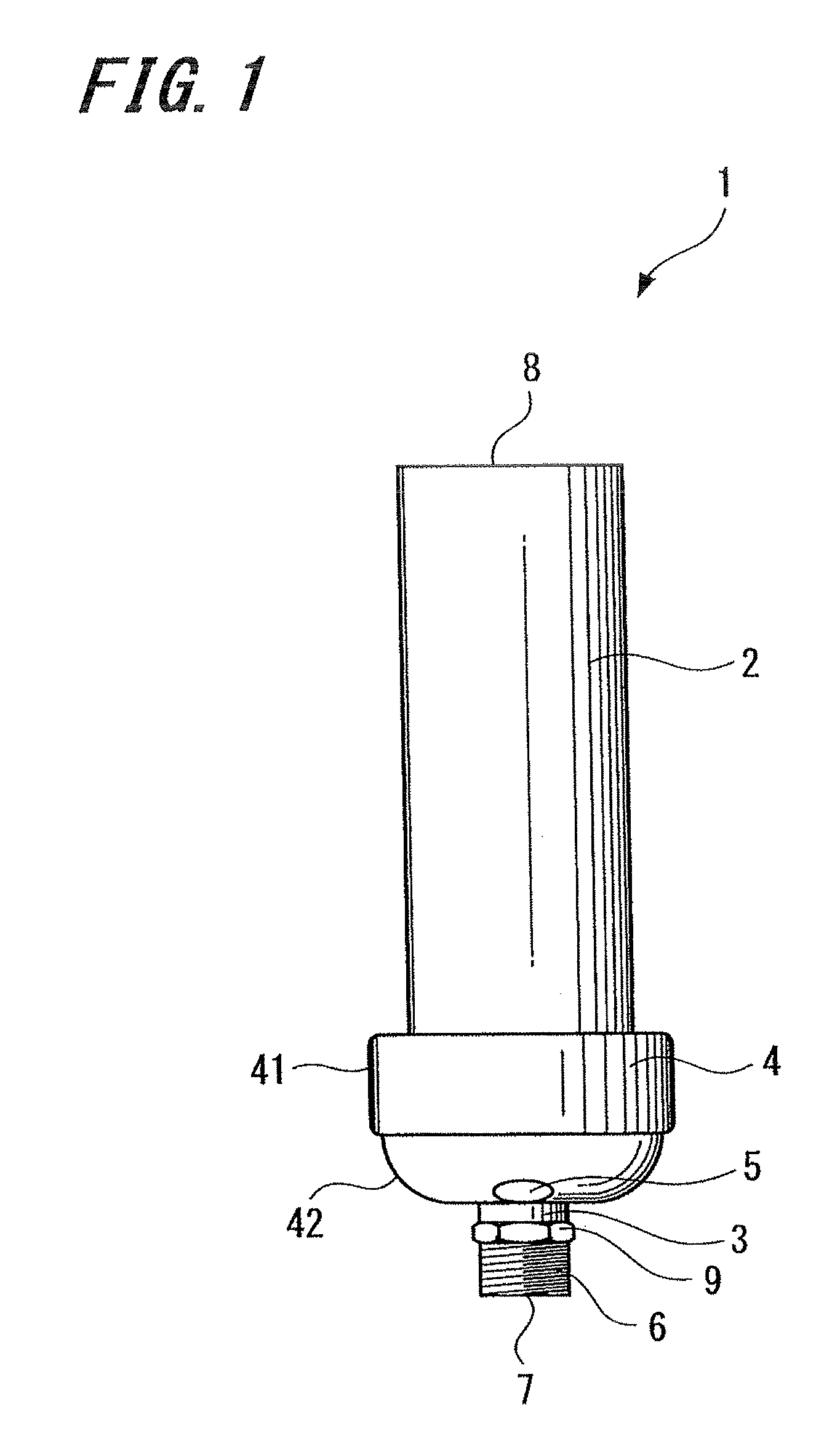
[0038]FIG. 1 is a schematic diagram illustrating the configuration of a fluid mixer 1 in accordance with one embodiment of the present invention.

[0039] As shown in FIG. 1, the fluid mixer 1 of the present embodiment includes a passage tube 2, a nozzle tube 3, and a coupling member 4 connecting the passage tube 2 and the nozzle tube 3.

[0040] The passage tube 2 includes a cylindrical tube member having a fluid passage inside thereof. An exhaust 8 is formed in one end (upper part) of the passage tube 2 and responsible for discharging a fluid passed through the inside of the passage tube to the outside.

[0041] The nozzle tube 3 includes a cylindrical tub...


PUM

PropertyMeasurementUnit
Flow rateaaaaaaaaaa

Abstract

Disclosed is a fluid mixer for mixing fluids of different types having a tube member in which a mixing portion for mixing the fluids of different types is installed and a nozzle member for introducing a fluid into the tube member. The nozzle member inn the fluid mixer includes a varying portion for varying a fluid flow.

Description

CROSS REFERENCES TO RELATED APPLICATIONS [0001] The present invention contains subject matter related to Japanese Patent Application JP 2006-272197 filed in the Japanese Patent Office on Oct. 3, 2006, the entire contents of which being incorporated herein by reference. BACKGROUND OF THE INVENTION [0002] 1. Field of the Invention [0003] The present invention relates to a fluid mixer for mixing different fluids. In particular, the present invention relates to a fluid mixer for use in treating water, such as industrial waste water, public and sewage water, an individual pond, a river, and ground water; removal and recovery of heterogeneous materials in gas; a bioreactor; and the like. In addition, the present invention relates to a fluid mixing apparatus using such a fluid mixer. Furthermore, the present invention relates to a nozzle member used in such a mixing apparatus. [0004] 2. Description of the Related Art [0005] The related-art fluid mixer mixes, stirs, and contacts fluids of d...

Claims


Application Information

Patent Timeline
IPC IPC(8): B01F15/04
CPCB01F3/04517B01F23/232311
Inventor KOJIMA, HISAO
Owner ANEMOS
Learn More