
Method, x-ray tube and imaging system for adjusting the position of the x-ray tube focus

a technology of x-ray tube and imaging system, which is applied in the direction of radiation beam directing means, instruments for radiation diagnostics, diaphragms, etc., can solve the problems of affecting the components of medical x-ray, x-ray radiation is very prone to external magnetic interference field, and unwanted displacement of the position, so as to minimize the influence of external magnetic interference field

Inactive Publication Date: 2008-04-03
SIEMENS HEALTHCARE GMBH
View PDF5 Cites 13 Cited by
  • Summary
  • Abstract
  • Description
  • Claims
  • Application Information

AI Technical Summary

Benefits of technology

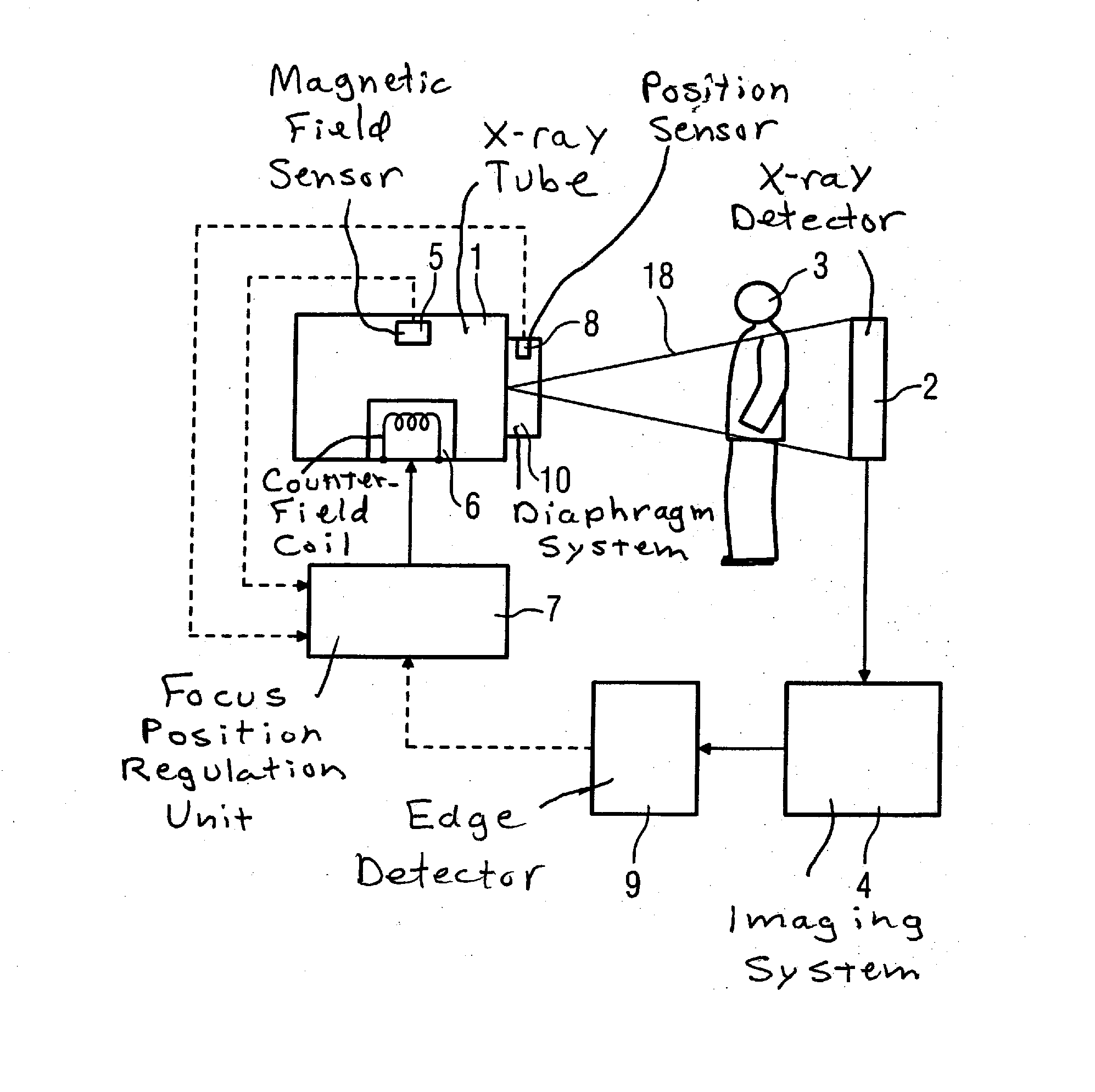
[0008] An object of the present invention is to provide a method that minimizes the influence of external magnetic interference fields on the position of the focus of an x-ray tube. Furthermore, it is an object of the invention to provide an x-ray tube as well as an x-ray acquisition system suitable for the implementation of the method.
[0009] The object is achieved in accordance with the invention by a method for adjustment of the position of a focus of an x-ray tube wherein the current focus position is corrected on the basis of a determination of the deviation of the current focus position from a target focus position or the determination of a measurement value proportional to the deviation, with the current focus position being adapted to the target focus position by reduction of the deviation or of the measurement value proportional to the deviation. In an embodiment of the invention, in this context it is particularly advantageous to regulate the deviation or the measurement value proportional to the deviation by repeated determination and correction to a value of essentially zero. The influence of external magnetic interference fields on the image quality and the unwanted displacement of the x-ray beam are thereby at least reduced, if not completely eliminated. Ferromagnetic shieldings can be reduced and weight can thus be saved. Less stressing of the mechanism and an interference-free image generation thus result, in particular in x-ray apparatuses with a moving C-arm or a rotating gantry.
[0010] A magnetic counter-field which at least reduces the magnetic field strength of the interference field is generated in an advantageous manner for a particularly effective reduction of influences of the interference field, at least at a sub-segment of the electron beam. At least one magnetic field coil or deflection coil preferably is used for generation of this counter-field. The strength of the magnetic field can be variably adjusted by means of such magnetic field coils or deflection coils. The magnetic coils are preferably arranged such that the magnetic field of the interference field can be two-dimensionally compensated.

Problems solved by technology

The magnetic field of the navigation system can lead to influences and disruptions of components of the medical x-ray acquisition system such as, for example, the x-ray tube.
In particular an electron beam that is directed, accelerated onto a rotatable anode plate of the x-ray tube to generate x-ray radiation is very prone to external magnetic interference fields.
The electron beam, whose impact point on the anode plate represents the focus point of the x-ray radiation, can be deflected from its intended path by such magnetic interference fields, such that it leads to an unwanted displacement of the position of the focus point and thus to an overall displacement of the generated x-ray beam.
Such devices have the disadvantage of exhibiting a high weight and magnetic field strengths in a magnetic field.
Primarily in the case of an x-ray apparatus with a moving C-arm or a quickly-rotating gantry, the weight and the magnetic field strength can lead to mechanical deflections and out-of-balances.

Method used


Image

  • Method, x-ray tube and imaging system for adjusting the position of the x-ray tube focus
  • Method, x-ray tube and imaging system for adjusting the position of the x-ray tube focus
  • Method, x-ray tube and imaging system for adjusting the position of the x-ray tube focus

Examples


Embodiment Construction

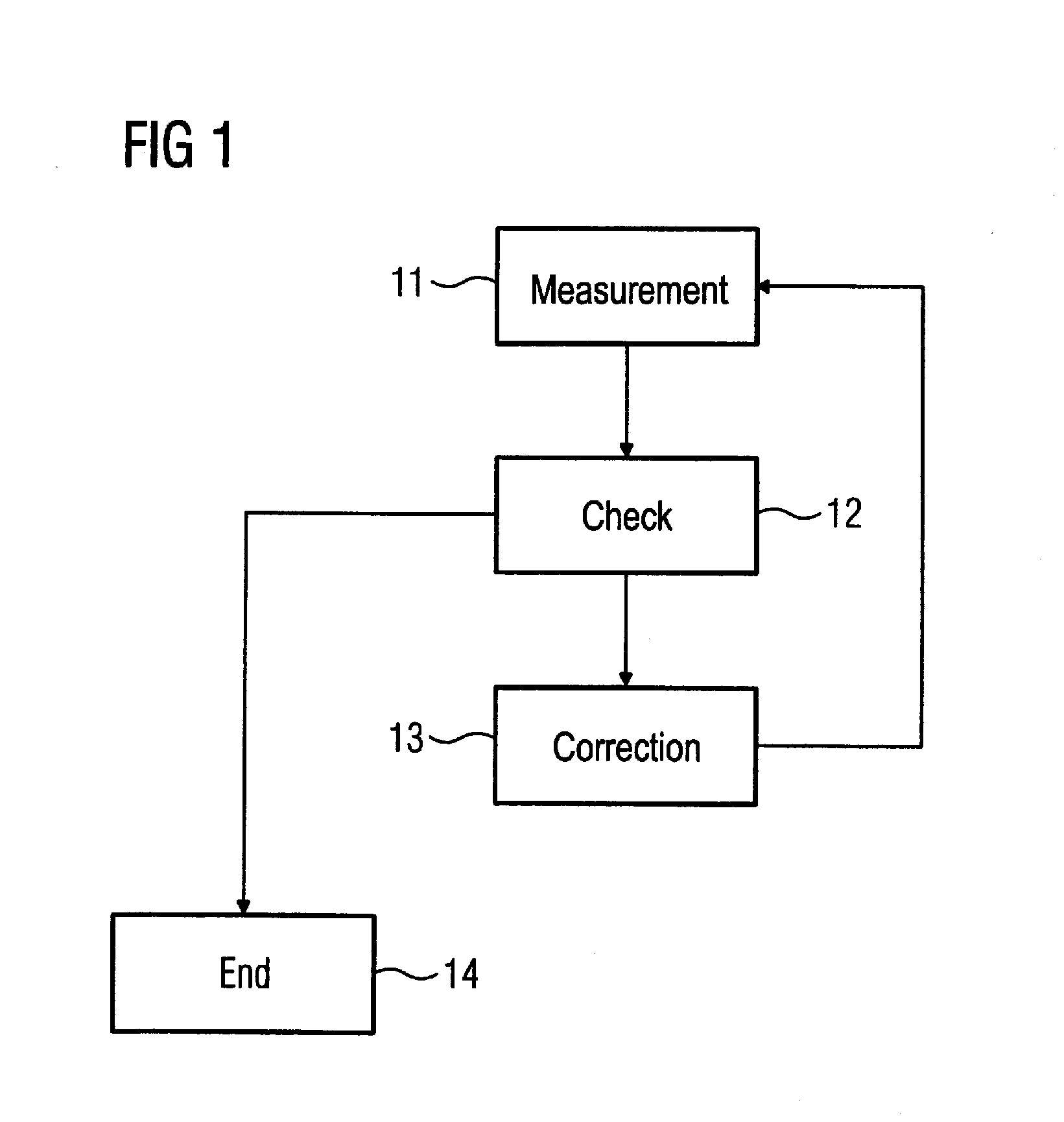
[0020] A simple workflow of a regulation method according to the invention is shown in FIG. 1 for adjustment of the position of a focus point of an x-ray tube, the focus position being displaced by a magnetic interference field. In a determination step 11, a deviation of a current focus position from a target focus position or a measurement value proportional to the deviation is determined.

[0021] For this purpose, at least one measurement is implemented, wherein either the current focus position of the focus point of the x-ray tube or a measurement value that is proportional to the deviation of the current focus position form a target focus position is measured. Such a measurement value can be formed, for example, from the magnetic field strength of the interference field. If the current focus position is measured, this is subsequently compared with the target focus position in order to obtain the deviation of the current focus position from the target focus position.

[0022] In a c...


PUM


Abstract

In order to reduce the influence of magnetic interference fields on the position of an x-ray focus of an x-ray tube, the deviation of a current focus position from a target focus position or of a measurement value proportional to the deviation is determined, the focus position by reducing the deviation of the current focus position from the target focus position, or the measurement value proportional to the deviation, on the basis of the determined deviation or the determined measurement value proportional to the deviation. The deviation of the current focus position from the target focus position or the measurement value proportional to the deviation is regulated to a value of essentially zero via repeated determination and correction.

Description

BACKGROUND OF THE INVENTION [0001] 1. Field of the Invention [0002] The present invention concerns: a method for adjustment of the position of a focus of an x-ray tube, the focus is unwontedly displaced by a magnetic interference field; and an x-ray tube for implementation of such a method, and a medical x-ray acquisition system with an x-ray tube operating according to such a method. [0003] 2. Description of the Prior Art [0004] For some years, medical x-ray acquisition systems have been used in connection with magnetic navigation systems for improved control of catheters and guidance wires in blood vessels. Such an overall system composed of a medical x-ray acquisition system and magnetic navigation is known, for example, from the brochure “Axiom Artis dFC Magnetic Navigation” from Siemens Medical Solutions, 2004. [0005] The magnetic field of the navigation system can lead to influences and disruptions of components of the medical x-ray acquisition system such as, for example, the...

Claims


Application Information

Patent Timeline
Patent Type & Authority Applications(United States)
IPC IPC(8): H01J35/14G21K1/08
CPCA61B6/06A61B6/08A61B6/586A61B6/587A61B6/4021A61B2019/2253A61B2019/5238H01J35/14H05G1/52A61B19/22A61B34/73A61B34/70A61B2090/376H01J35/153
Inventor BERNHARDT, JENSMEYER, ANDREASNEKOVAR, ANTON
Owner SIEMENS HEALTHCARE GMBH
Learn More