Rail track tie

a track tie and rail technology, applied in the field of rail track tie, can solve the problems of unsatisfactory attenuation of mechanical vibration when a train passes over such a track system as presently known, and achieve the effect of limiting fatigue and stress, and improving vibration attenuation performan

Inactive Publication Date: 2008-04-10
ALSTOM TRANSPORT SA
View PDF9 Cites 37 Cited by
  • Summary
  • Abstract
  • Description
  • Claims
  • Application Information

AI Technical Summary

Benefits of technology

[0011] An object of the invention is to improve the vibration attenuation performance of the above-mentioned tie, in particular in a range of frequencies up to 250 hertz (Hz), which is considered as being capable of generating nuisance for surrounding buildings, while also limiting the fatigue and the stress to which the rail system is subjected.

Problems solved by technology

However, the attenuation of mechanical vibration when a train is passing over such a track system as presently known is not entirely satisfactory.

Method used


Image

  • Rail track tie
  • Rail track tie
  • Rail track tie

Examples


first embodiment

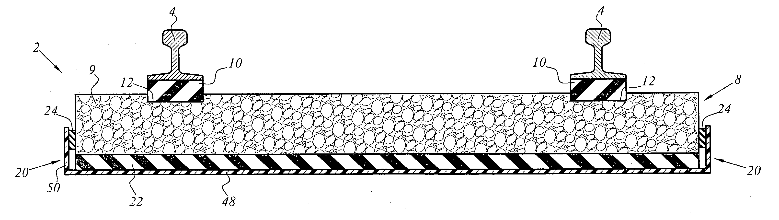
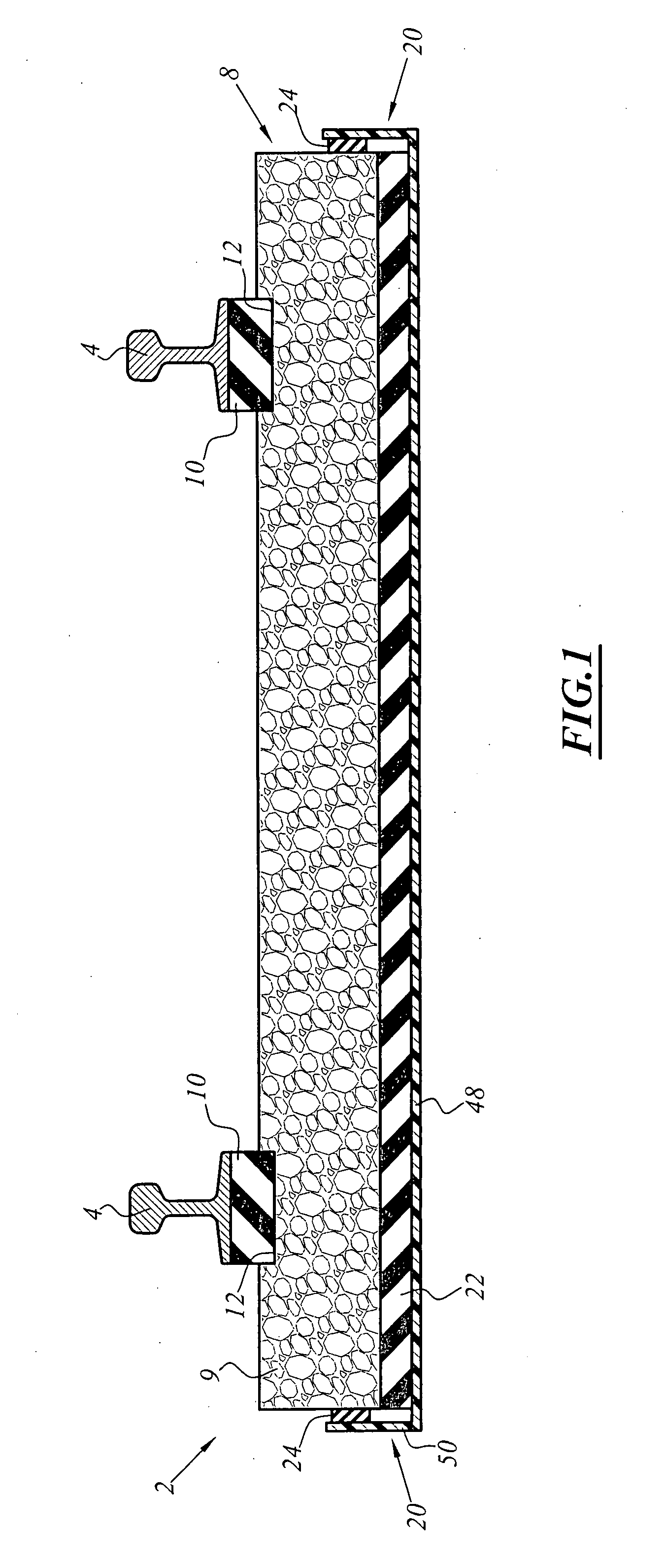
[0030] A segment 2 of rail track in the invention is shown diagrammatically in FIG. 1. The segment 2 comprises two longitudinal rails 4 fastened on a tie 8. The tie 8 comprises a single rigid concrete block 9 and two resilient bearing elements 10 disposed between each rail 4 and the block 9.

[0031] By convention, the longitudinal rails 4 define a reference for the longitudinal direction.

[0032] The resilient bearing elements 10 are substantially in the form of rectangular parallelepipeds. In the example shown in FIG. 1, their width is substantially equal to the width of the base of the rail 4, and their length is substantially equal to the width of the block 9.

[0033] The resilient bearing elements 10 are received in respective recesses 12 in the block 9. The profile of each recess 12 in cross-section is substantially rectangular. The width and the length of each recess 12 in the example shown in FIG. 1 are substantially equal to the width and the length respectively of a resilient b...

second embodiment

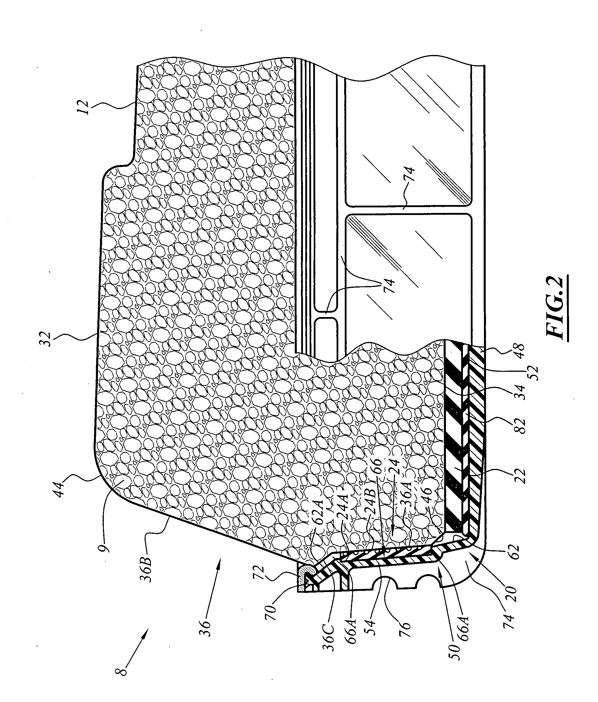
[0085] In a second embodiment shown in FIG. 6, the tie 108 comprises two rigid blocks 109 interconnected by a spacer 184. Insofar as the two-block tie 108 is very similar to the single-block tie 8, the same references are used in FIG. 6 as the references used in FIGS. 1 to 4, but with the addition of 100.

[0086] The length of the covers 120 is adapted to receive the blocks 109. The same applies to the transverse pads 126 and the resilient soleplates 122. FIGS. 2 and 3 which show a single-block tie 8 are also entirely applicable for illustrating a tie 108.

[0087] The main difference between the single-block tie 8 and the two-block tie 108 lies in the presence of a spacer 184 penetrating into the two blocks 109.

[0088] The reduction in the dynamic stiffness k2 of the resilient soleplates 122 and / or the increase in the weight of the blocks 109 generate a large longitudinal bending movement.

[0089] Thus, the spacer 184 is of a shape adapted to obtain a second moment of area that is large...


PUM


Abstract

The rail track tie including: a rigid block presenting a bottom face, and a top face for receiving at least one longitudinal rail; a cover for receiving the rigid block and in the form of a rigid shell including a bottom and a peripheral rim around the bottom; and a resilient soleplate disposed between the bottom face of the rigid block and the bottom of the cover. The resilient soleplate has dynamic stiffness k2 lying in the range of 6 kN/mm to 10 kN/mm, and preferably in the range of 6 kN/mm to 8 kN/mm.

Description

[0001] The present invention relates to a rail track tie or “sleeper”, of the type comprising: [0002] a rigid block presenting a bottom face, and a top face for receiving at least one longitudinal rail; [0003] a cover for receiving the rigid block and in the form of a rigid shell comprising a bottom and a peripheral rim around the bottom; and [0004] a resilient soleplate disposed between the bottom face of the rigid block and the bottom of the cover. BACKGROUND OF THE INVENTION [0005] Such ties are frequently used for laying a rail track without ballast, e.g. in or on a structure such as a tunnel or a viaduct, where the ties are supported by a bed or a slab. [0006] EP-A-0 919 666 describes a tie of this type. The rigid cover is embedded in a concrete slab, and together therewith it forms a rigid assembly. [0007] Each rail generally rests on a resilient bearing element, disposed between each rail and the rigid block. The resilient bearing elements thus form a first elastic stage. The...

Claims


Application Information

Patent Timeline
Patent Type & Authority Applications(United States)
IPC IPC(8): E01B3/00E01B1/00
CPCE01B1/005E01B3/44E01B3/40E01B9/68E01B2204/01
Inventor GIRARDI, MARCELPETIT, CHARLESLE CORRE, FREDERICROBERTSON, IAN
Owner ALSTOM TRANSPORT SA
Why Eureka
Try Eureka