
Handheld sprayer with removable cartridge and method of using same

Inactive Publication Date: 2008-04-10
EFIELD INNOVATIONS
View PDF31 Cites 22 Cited by
  • Summary
  • Abstract
  • Description
  • Claims
  • Application Information

AI Technical Summary

Benefits of technology

[0014]Optionally, the handle comprises a grip for engaging a user's hand. In the present context, the grip is the portion of the handle that comes into contact with the user's hand. At least a portion of the grip (such as the trigger or related control member) can be made from a material such as a metal, an electrically conductive plastic, electrically conductive polymer, electrically conductive rubber or combination thereof. This facilitates grounding of the spray device through the user. The trigger can be used to commence and halt operation of the spray device. In another option, a longitudinal dimension of the handle and a longitudinal dimension of the cartridge are substantially aligned along a common longitudinal axis, while in another, they are angularly disposed relative to one another in an offset manner, thereby enhancing ergonomic features of the spray device. In the offset configuration, the angle formed between the longitudinal dimensions is up to thirty degrees. In either configuration, the center of gravity of the cartridge and the handle is located along a segment of the grip during at least a portion of operation of the spray device, thereby improving balance. The cartridge may be rotatably positionable about its longitudinal axis such that a preferred spraying pattern made be employed while keeping the user's hand position relatively constant. The cartridge can be rotated in angles of up to plus or minus ninety degrees from a neutral position (i.e., the position assumed by the cartridge upon normal connection with the handle of the spray device). The spray device may further include a frame substantially similar to that described previously. An interface defined between the cartridge and the handle may include a load-bearing mounting surface on the handle that cooperates with a complementary

Problems solved by technology

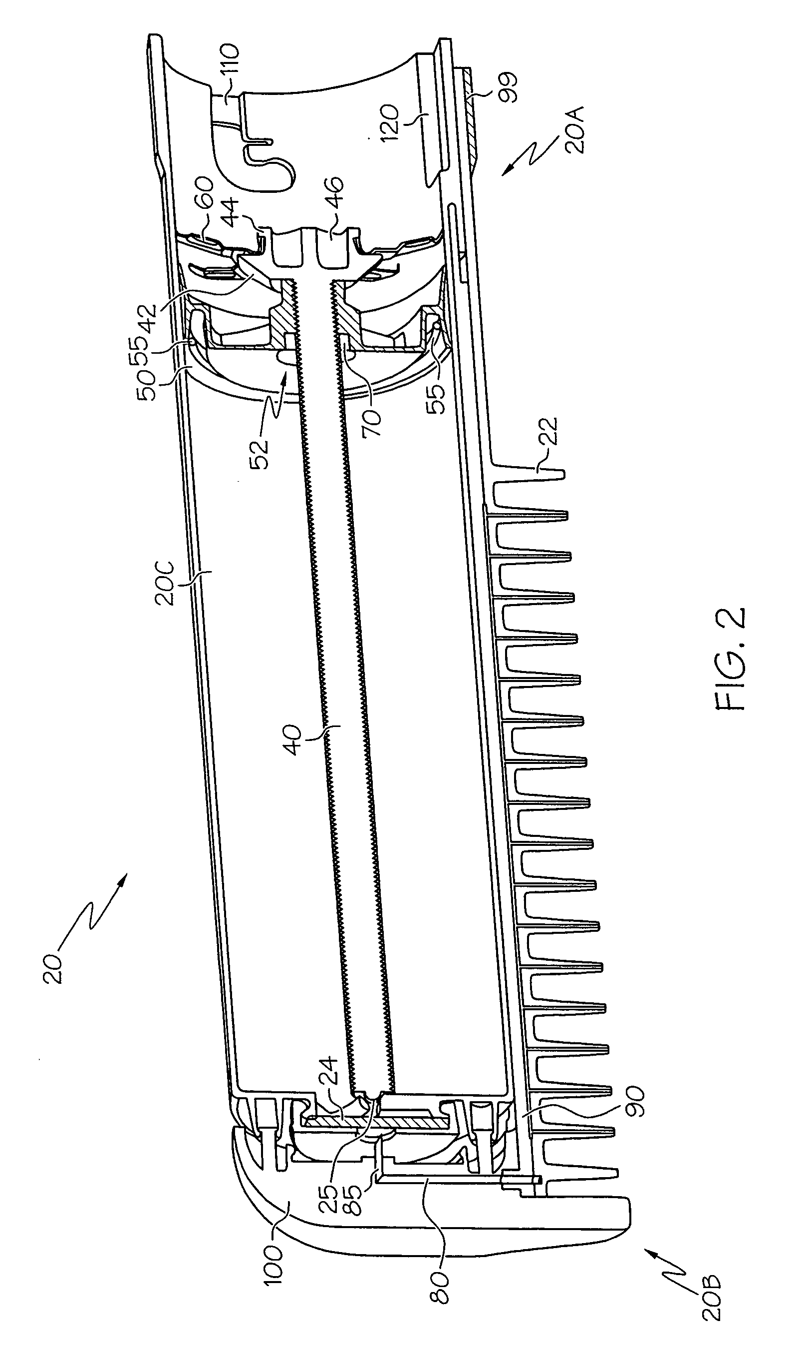
Unfortunately, the above-mentioned cartridge is prone to leakage, especially in regions between the outer periphery of the piston and the inner wall of the cartridge, as well as the threaded space between the screw and the piston.
In an application where a cartridge of this type may be used in a device with electronics, the fluid can potentially leak into regions where electronic a

Method used


Image

  • Handheld sprayer with removable cartridge and method of using same
  • Handheld sprayer with removable cartridge and method of using same
  • Handheld sprayer with removable cartridge and method of using same

Examples


Embodiment Construction

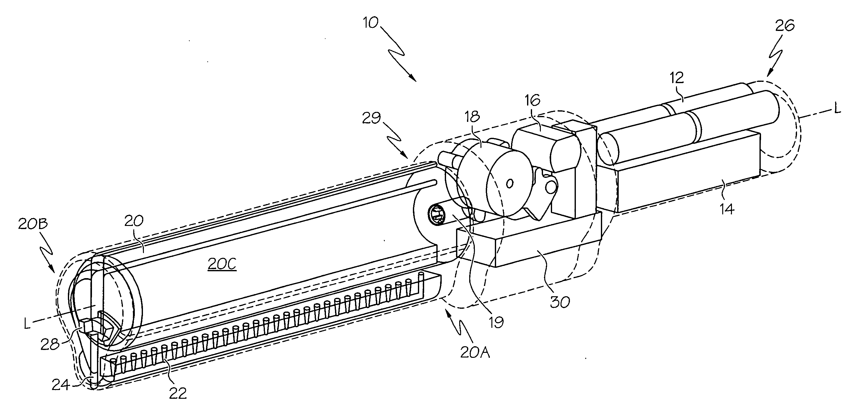
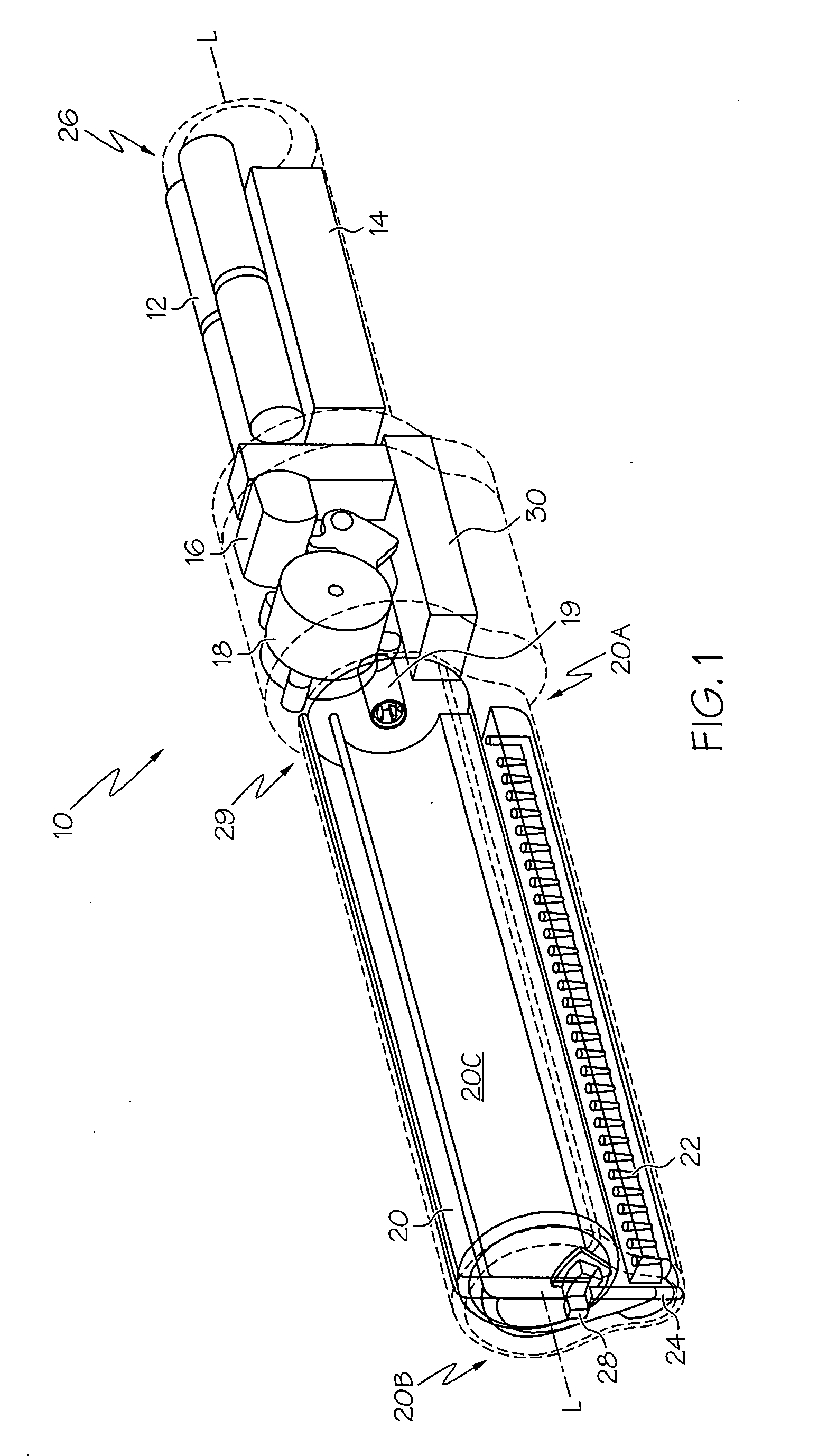
[0041]Referring first to FIGS. 1 and 13, a sprayer 10 includes a handle 26, a cartridge interface 29 and fluid-containing cartridge 20. An array of nozzles 22 are situated beneath cartridge 20, and are in fluid communication therewith to dispense a fluid. The handle 26 is used to house a power supply 12, a converter (also referred to as an electronics or circuit board) 14, a motor 16, a drive mechanism 18 and driver 19, and a high voltage multiplier 30 (also referred to as a voltage multiplier circuit). In the present context, the term “high voltage” and its variants is used to represent increases in voltage over that provided by the power supply 12 due to the operation of the voltage multiplier 30, rather than as indicia of a particular voltage level. By way of example, for a voltage measured at the output of the power supply 12 of six volts, a voltage of thousands of volts measured at the output of the voltage multiplier 30 would constitute a high voltage. The power supply 12 may ...


PUM


Abstract

A cartridge for a handheld electrohydrodynamic (EHD) spraying device and a spraying device incorporating the cartridge. The cartridge is disposable, and can contain therapeutic products. The device includes a wetted lead screw with a compliant seal, where the placement of the seal relative to the screw inhibits leakage during both cartridge use and storage. A frame disposed within the cartridge acts as a load-transferring mechanism for the weight of the cartridge to a handle of the spraying device.

Description

[0001]This application claims the benefit of the filing date of U.S. Design Patent Application entitled HANDLE, (application Ser. No. 29 / 261,411, Attorney Docket No. 15237USR / BAT0109DA), and U.S. Design Patent Application entitled HANDLE, (Application Ser. No. 29 / 261,452, Attorney Docket No. 14841USR1 / BAT0115DA), both filed Jun. 13, 2006.BACKGROUND OF THE INVENTION[0002]The present invention relates generally to devices for spraying finely dispersed liquids, and more particularly to the use of a disposable cartridge that is compatible with a handheld electrohydrodynamic (EHD) spray device.[0003]Spraying using EHD technology (also referred to as electric field effect technology (EFET)) is a process where fluids or other bulk solutions are dispensed through electrically-charged nozzles. In an EHD spray nozzle, the material to be sprayed flows through a region of high electric field strength made possible by the application of a high voltage to the nozzles and associated nozzle geometr...

Claims


Application Information

Patent Timeline
IPC IPC(8): F23D11/32
CPCB05B9/0838B05B5/1691
Inventor LIND, JAMES J.TREES, GREGORYZAMBANINI, JOSEPH E.GRAHAM, BRIANHARPHAM, R. READE
Owner EFIELD INNOVATIONS
Learn More