
Vacuum container for cooled magnetic resonance probe head

a magnetic resonance and vacuum container technology, applied in the field of magnetic resonance probe heads, can solve problems such as deteriorating efficiency/filling factor, and achieve the effects of improving thermal flow, good magnetic field homogeneity, and simple production

Active Publication Date: 2008-04-10
BRUKER SWITZERLAND AG
View PDF16 Cites 9 Cited by
  • Summary
  • Abstract
  • Description
  • Claims
  • Application Information

AI Technical Summary

Benefits of technology

[0017]The RF resonator coils can be moved more closely to the test sample, in particular in the y-direction, since the temperature control gap is omitted. This is accompanied by a reduction in coil volume (for a given measuring volume), which increases the efficiency / fill factor of the RF resonator coils. This improves the signal-to-noise ratio of the magnetic resonance probe head, and reduces the pulse times for the same pulse angle with equal power.
[0053]In a further embodiment of an inventive magnetic resonance probe head, the recess for the test sample is substantially cylindrical, with the cylinder axis extending in the z direction, thereby providing high homogeneity of the magnetic field in the test sample.

Problems solved by technology

The ventilation gap represents part of the coil volume which cannot be filled by the test sample, and therefore always deteriorates the efficiency / filling factor.

Method used


Image

  • Vacuum container for cooled magnetic resonance probe head
  • Vacuum container for cooled magnetic resonance probe head
  • Vacuum container for cooled magnetic resonance probe head

Examples


Embodiment Construction

[0077]The invention concerns a vacuum container for a cooled magnetic resonance probe head.

[0078]The sensitivity of high-resolution nuclear magnetic resonance (NMR) spectroscopy and NMR microscopy has been substantially increased recently by using cooled magnetic resonance probe heads.

[0079]The receiver coils and the receiving electronics of these probe heads are usually cooled to cryogenic temperatures, i.e. temperatures below 100 K. Cooling reduces thermal noise of the resistive elements and also the RF resistance of metals. It moreover enables use of superconductors for the transmitting / receiver coils. Cooled electronics can be produced with a lower noise temperature than conventional electronics.

[0080]One of the major problems of cooled magnetic resonance probe heads is the requirement to achieve cryogenic temperatures for the transmitting / receiver coils and at the same time maintain the test samples close to room temperature (−40 to +200° C.), since the test substances (or test...


PUM

PropertyMeasurementUnit
diameteraaaaaaaaaa
static magnetic fieldsaaaaaaaaaa
temperatureaaaaaaaaaa

Abstract

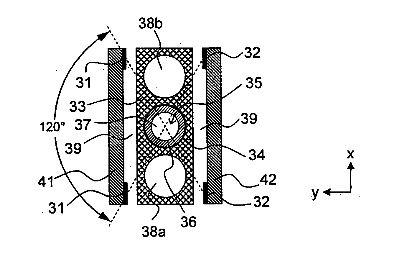
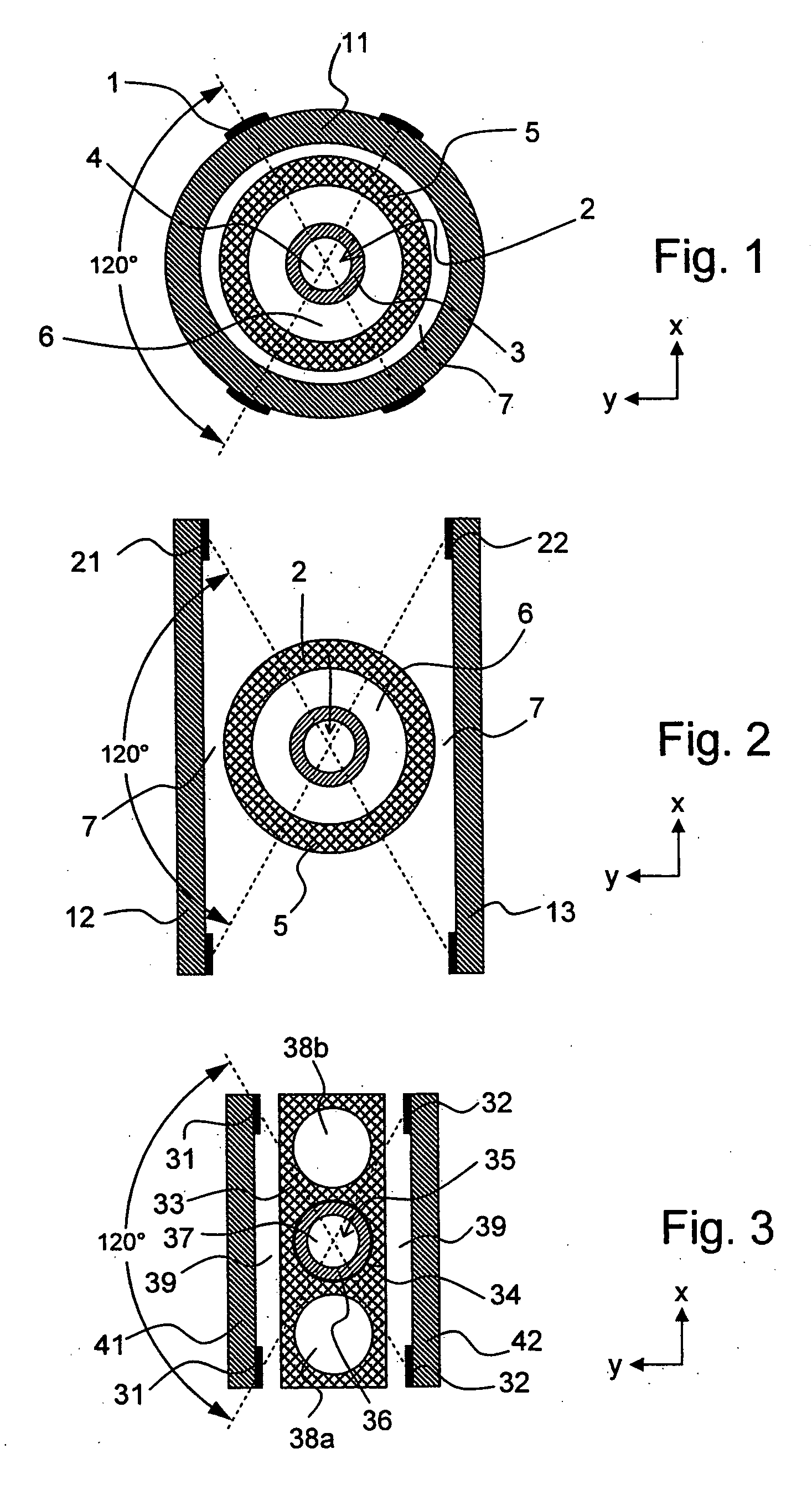
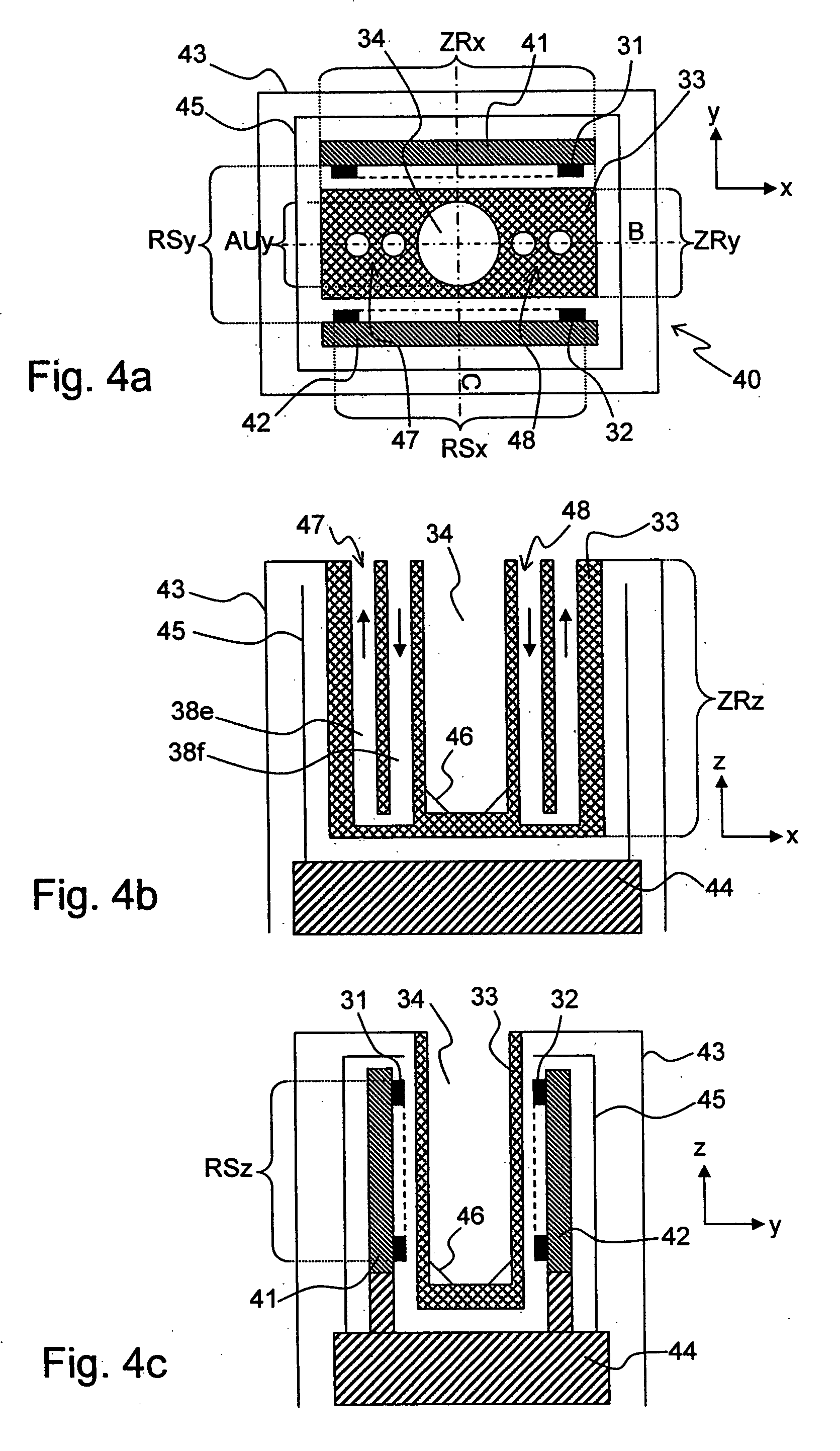
A magnetic resonance probe head (40) comprises a vacuum container (43) in which several RF resonator coils (31, 32; 51-54, 61-64) are disposed that can be cryogenically cooled and which are each designed as planar coils disposed parallel to a z direction. All of the RF resonator coils (31, 32; 51-54, 61-64) have a larger extension in an x direction (RSx) than in a y direction (RSy), wherein the x, y, z directions form a rectangular coordinate system. A central tube block (33; 81; 111; 121; 171; 181) is disposed between the RF resonator coils (31, 32; 51-54, 61-64) and has a recess (34, 112, 122) for a test sample (35), which is elongated in the z direction. The central tube block (33; 81; 111; 121; 171; 181) partially delimits the vacuum container and the recess (34, 112, 122) is disposed outside of the vacuum container (43). The central tube block (33; 81; 111; 121; 171; 181) has a larger extension in the x direction (ZRx) than in the y direction (ZRy) in the area between the RF resonator coils (31, 32; 51-54, 61-64). The inventive probe head improves the sensitivity, in particular, for small and round test samples.

Description

[0001]This application claims Paris Convention priority of DE 10 2006 046 888.0 filed Oct. 4, 2006 the complete disclosure of which is hereby incorporated by reference.BACKGROUND OF THE INVENTION[0002]The invention concerns a magnetic resonance probe head, comprising[0003]a vacuum container in which several RF resonator coils are disposed, which can be cryogenically cooled and which are each designed as planar coils disposed parallel to a z direction, wherein the overall RF resonator coils have a longer extension in the x direction than in the y direction, the x, y, z directions forming a rectangular coordinate system,[0004]a central tube block disposed between the RF resonator coils and having a recess for a test sample, which is elongated in the z direction, wherein the central tube block partially delimits the vacuum container, and the recess is located outside of the vacuum container.[0005]A magnetic resonance probe head of this type is disclosed e.g. in ref. [5].[0006]Nuclear m...

Claims


Application Information

Patent Timeline
Patent Type & Authority Applications(United States)
IPC IPC(8): G01R33/28G01N24/08
CPCG01R33/307G01R33/31G01R33/34023G01R33/3415G01R33/34061G01R33/34092G01R33/3403
Inventor FREYTAG, NICOLAS
Owner BRUKER SWITZERLAND AG
Learn More