Lighting device and lighting method

a technology of lighting device and light source, which is applied in the direction of discharge tube/lamp details, lighting and heating apparatus, discharge tube luminescnet screens, etc., can solve the problem of difficult manufacturing, and achieve the effect of wide gamut, good color rendering index, and high efficiency

Active Publication Date: 2008-04-10
IDEAL IND LIGHTING LLC
View PDF100 Cites 321 Cited by
  • Summary
  • Abstract
  • Description
  • Claims
  • Application Information

AI Technical Summary

Benefits of technology

[0025] There is an ongoing need for a high efficiency white light source that combines the efficiency and long life of white solid state lamps, e.g., LED lamps (i.e., ...

Problems solved by technology

In addition, it has been found that in general, lumiphors which contain phosphor particles of larger sizes tend to...

Method used


Image

  • Lighting device and lighting method
  • Lighting device and lighting method
  • Lighting device and lighting method

Examples


Embodiment Construction

[0062] The present invention now will be described more fully hereinafter with reference to the accompanying drawings, in which embodiments of the invention are shown. However, this invention should not be construed as limited to the embodiments set forth herein. Rather, these embodiments are provided so that this disclosure will be thorough and complete, and will fully convey the scope of the invention to those skilled in the art. Like numbers refer to like elements throughout. As used herein the term “and / or” includes any and all combinations of one or more of the associated listed items.

[0063] The terminology used herein is for the purpose of describing particular embodiments only and is not intended to be limiting of the invention. As used herein, the singular forms “a”, “an” and “the” are intended to include the plural forms as well, unless the context clearly indicates otherwise. It will be further understood that the terms “comprises” and / or “comprising,” when used in this s...


PUM


Abstract

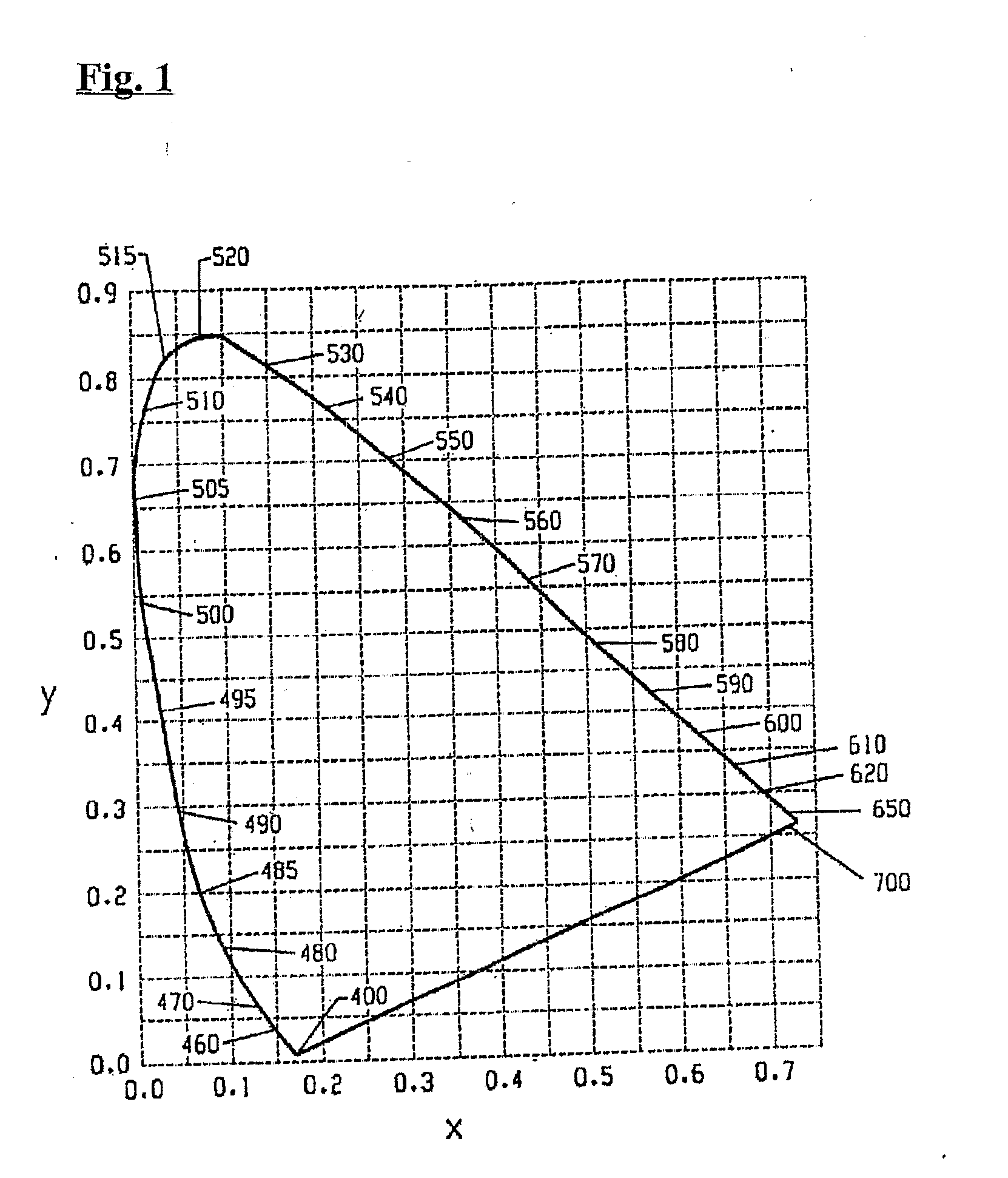
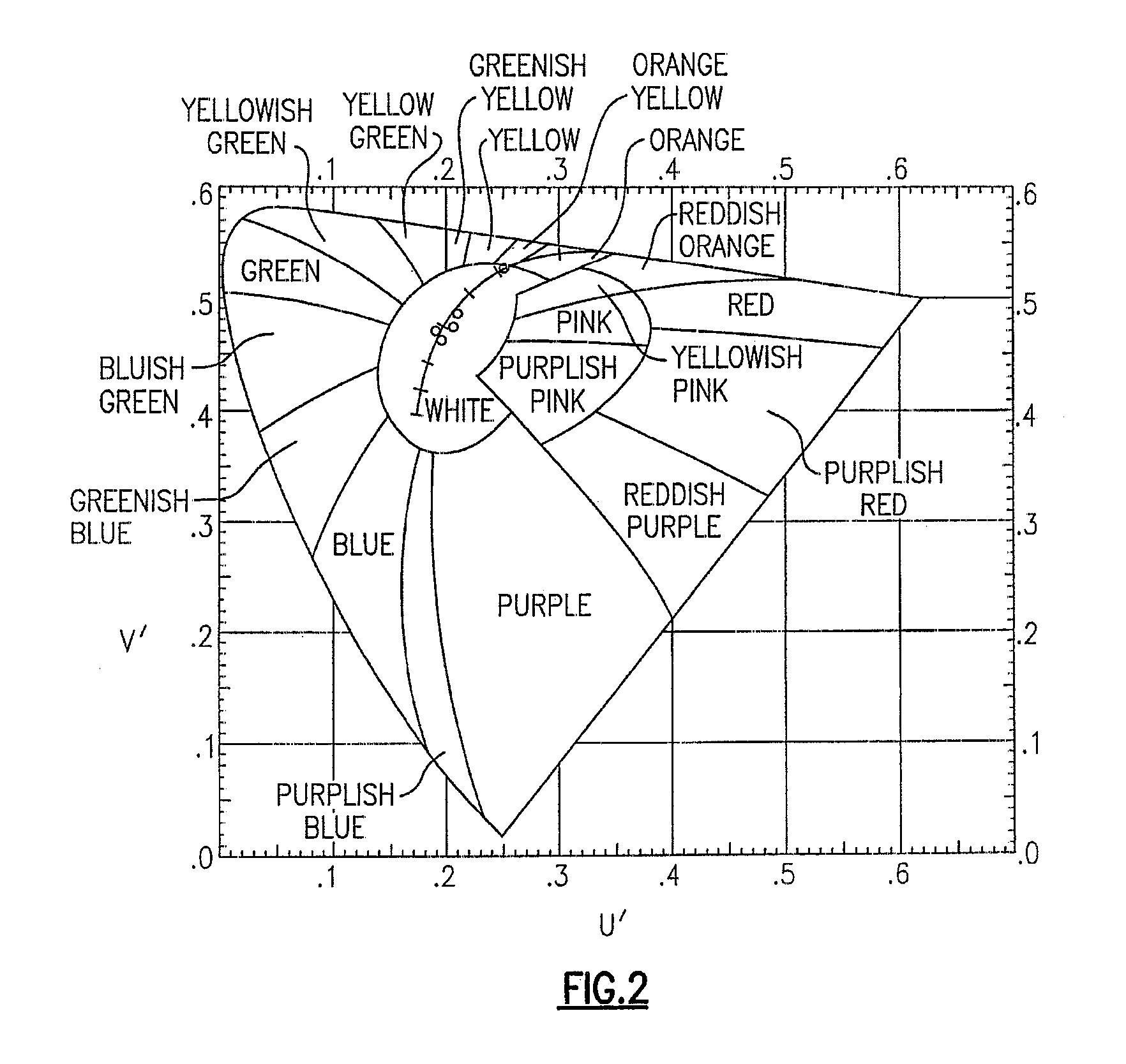
A lighting device comprising at least one solid state light emitter and at least one lumiphor. If each solid state light emitter is illuminated and each lumiphor is excited, a mixture of light emitted has x, y color coordinates within an area defined by the coordinates 0.32, 0.40; 0.36, 0,48; 0.43, 0.45; 0.42, 0.42; and 0.36, 0.38. The lumiphor(s) comprises phosphor particles, in the range of from 3 to 7 micrometers (or 5-15, 10-20, or 15-25 micrometers), or having a mean particle size of 5, 10, 15, 20 micrometers. Also, a lighting device comprising at least one emitter and at least one lumiphor in which the lumiphor comprises phosphor particles having sizes as mentioned above, where the lighting device has an efficacy of at least 60 (or 70, or 80) lumens per watt.

Description

CROSS-REFERENCE TO RELATED APPLICATIONS [0001] This application claims the benefit of U.S. Provisional Patent Application No. 60 / 839,453, filed Aug. 23, 2006, the entirety of which is incorporated herein by reference.FIELD OF THE INVENTION [0002] The present invention relates to a lighting device, in particular, a device which includes one or more light emitting diodes and one or more luminescent materials (e.g., one or more phosphors). The present invention is also directed to lighting methods. BACKGROUND OF THE INVENTION [0003] A large proportion (some estimates are as high as twenty-five percent) of the electricity generated in the United States each year goes to lighting. Accordingly, there is an ongoing need to provide lighting which is more energy-efficient. It is well-known that incandescent light bulbs are very energy-inefficient light sources—about ninety percent of the electricity they consume is released as heat rather than light. Fluorescent light bulbs are more efficien...

Claims


Application Information

Patent Timeline
IPC IPC(8): F21V9/16H01L33/50
CPCH01L33/502H01L2224/48091H01L2224/48247H01L2224/8592H01L2924/00014H01L2924/00011H01L2924/01032
Inventor VAN DE VEN, ANTONY PAULNEGLEY, GERALD H.
Owner IDEAL IND LIGHTING LLC
Why Eureka
Try Eureka