
Optical glass

a technology of optical glass and refractive index, applied in the field of ultralow refractive index and ultralow dispersion glass, can solve the problems of high productivity, difficult to produce homogeneous glass stably, and hinder glass production

Inactive Publication Date: 2008-04-10
OHARA
View PDF8 Cites 7 Cited by
  • Summary
  • Abstract
  • Description
  • Claims
  • Application Information

AI Technical Summary

Benefits of technology

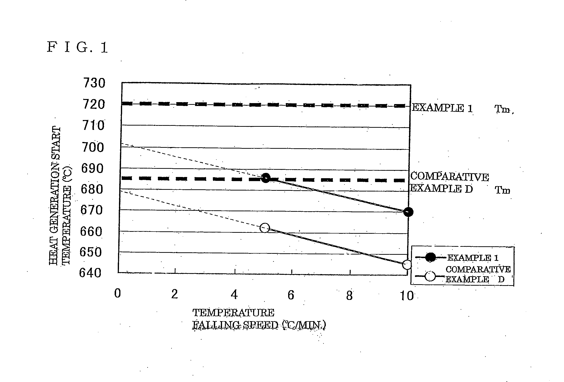
[0007] For achieving the above object of the invention, studies and experiments made by the inventors of the present invention have resulted in the finding, which has led to the present invention, that occurrence of devitrification in the inside portion of glass during cooling of the glass after melting can be effectively prevented while desired refractive index and Abbe number can be maintained by adjusting the ratio (Si+B+P+Al) / F in mass % on element basis to a value within a range from 0.20 to 0.40 in a glass material composition comprising P, Al, Ca, Sr, Ba, Y, F and O and adjusting the composition ratio of the component elements.

Problems solved by technology

Since, however, glass containing a large amount of fluorine component is inferior in resistance to devitrification, devitrification occurs during cooling of a glass melt with the result that it is difficult to produce a homogeneous glass stably in a large scale production and this hinders production of the glass with high productivity.
No sufficient consideration has been made in these literature for improving resistance to devitrification during a long period of time which can be applied to a continuous melting and glass-forming production system which has high productivity.
In this method, however, if it is desired to obtain a large-size glass material while maintaining a high glass casting temperature, glass forming has to be made in a low viscosity region and this will cause difficulty in controlling the flow amount of glass precisely and, as a result, a non-uniform striped portion (striae) tends to be produced by the flow of glass.
Besides, since glass has small heat conductivity, the inside portion of the glass which is difficult to cool compared with the surface portion of the glass has longer time during which the glass is subject to devitrification.
Thus, there is likelihood that devitrification occurs in the inside portion of the glass and, therefore, improvement in this literature against devitrification cannot be said sufficient.

Method used


Image

  • Optical glass

Examples


examples

[0130] Examples of the optical glass of the present invention will be described below. It should be understood that the scope of the present invention is in no way restricted to these examples.

[0131] Tables 1 to 4 show amounts in mass % on element basis of elements constituting glass materials (Aspects 4-6), the ratio (Si+B+P+Al) / F in mass % on element basis, the ratio Ba / Sr, refractive index (nd), Abbe number (νd), and a result of a constant temperature test (Tm−Tx) of Example Nos. 1-23 for obtaining a ultra-low refractive index and ultra-low dispersion fluoro-complex phosphate glass having a refractive index (nd) within a range from 1.41 to 1.47 and an Abbe number (νd) within a range from 90 to 100. Tables 5 to 8 show amounts in mass % of glass materials (Aspects 7-9), the ratio (MgF2+CaF2) / (Al(PO3)3+AlF3) in mass % of the respective examples. In other words, the examples of Tables 5 to 8 are of the same composition as the corresponding examples expressed in a different manner.

[...


PUM

PropertyMeasurementUnit
Abbe numberaaaaaaaaaa

Abstract

An optical glass having a refractive index (nd) within a range from 141 to 1.47 and an Abbe number (νd) within a range from 90 to 100 comprises in mass % on element basis: P 0.1-5.0%Al 1.0-20.0%F30.0-60.0% andO 1.0-20.0%and comprises, as an essential component, one or more elements selected from the group consisting of Ca, Sr and Ba. In this optical glass, the ratio (Si+B+P+Al) / F is within a range from 0.15 to 0.40.

Description

BACKGROUND OF THE INVENTION [0001] This invention relates to a ultra-low refractive index and ultra-low dispersion glass having a refractive index (nd) of 1.41-1.47 and an Abbe number (νd) of 90-100 and optical elements such as lenses and prisms which are obtained by using this glass. More particularly, this invention relates to a raw material composition and a manufacturing method which can effectively prevent devitrification (precipitation of crystals) which occurs during cooling from a molten state of glass which is a serious problem in manufacture of a glass. The invention provides glass materials suitable for use as projection lenses and prisms of optical instruments represented by a camera and a projector for which a high precision chromatic aberration characteristic is required. The invention also provides optical elements and optical instruments using the optical glass of the invention. [0002] A low refractive index and low dispersion glass material has a characteristic that...

Claims


Application Information

Patent Timeline
Patent Type & Authority Applications(United States)
IPC IPC(8): C03C3/15
CPCC03C3/247C03C1/00
Inventor SUZUKI, JUNKOONOZAWA, MASAHIRO
Owner OHARA
Learn More