Intravascular stent

a stent and crimping technology, applied in the field of vascular repair devices, can solve the problems of increasing the damage of the drug coating on the stent in this crimping configuration, increasing the difficulty in designing a stent, and the drug coating in certain regions of the stent becoming non-uniform, so as to reduce the likelihood of contact

Inactive Publication Date: 2008-04-10
ABBOTT CARDIOVASCULAR
View PDF99 Cites 8 Cited by
  • Summary
  • Abstract
  • Description
  • Claims
  • Application Information

AI Technical Summary

Benefits of technology

[0010]The present invention includes stent designs that reduce the likelihood of contact among structural members when the stent diameter is reduced prior to insertion into the body. In one embodiment, a flexible intravascular stent for use in a body lumen has cylindrical rings aligned along a common longitudinal axis. The rings are interconnected to form the stent. Each cylindrical ring has a first delivery diameter for insertion into the body, and an expanded second diameter after being implanted into the body.
[0012]The stent design may also include structural features that improve such aspects as flexibility, the coatibility of a drug coating onto the stent, flare reduction, and stent retention within the body.
[0014]Another embodiment further improves retention of the stent within the body. In this embodiment, a flexible intravascular stent has a plurality of cylindrical rings aligned along a common longitudinal axis and interconnected to form the stent. Each cylindrical ring has a first delivery diameter and a second implanted diameter. At least some of the cylindrical rings have first peaks and second peaks, each of the peaks having a height, the second peaks being shorter than the first peaks. The stent also has an end ring having a plurality of first peaks and second peaks having a height, the height of the first and second peaks being uniform.
[0015]Another embodiment of the invention reduces the minimum diameter of the stent when it is crimped, prior to insertion into the body. In this embodiment, a flexible intravascular stent has a plurality of cylindrical rings aligned along a common longitudinal axis. At least one link connects adjacent cylindrical rings. The stent has a proximal end ring, which has five symmetric crests of equal height. The stent may optionally have different cell designs, with a first cell having two long crests and one short crest, and a second cell having one long crest and one short crest.

Problems solved by technology

Further, it is well known that the stent (usually made from a metal) may require a primer material coating to provide a substrate on which a drug or therapeutic agent is coated, since some drugs and therapeutic agents do not readily adhere to a metallic surface.
In the scenario of FIG. 7, even more of the drug coating on the stent is damaged in this crimped configuration.
It is a considerable challenge to design a stent pattern that will avoid metal-to-metal contact.
That is, the greater radii helps reduce what is known in the art as “webbing.” Webbing is a well known problem in which the drug coating in certain regions of the stent becomes non-uniform.

Method used


Image

  • Intravascular stent
  • Intravascular stent
  • Intravascular stent

Examples


Embodiment Construction

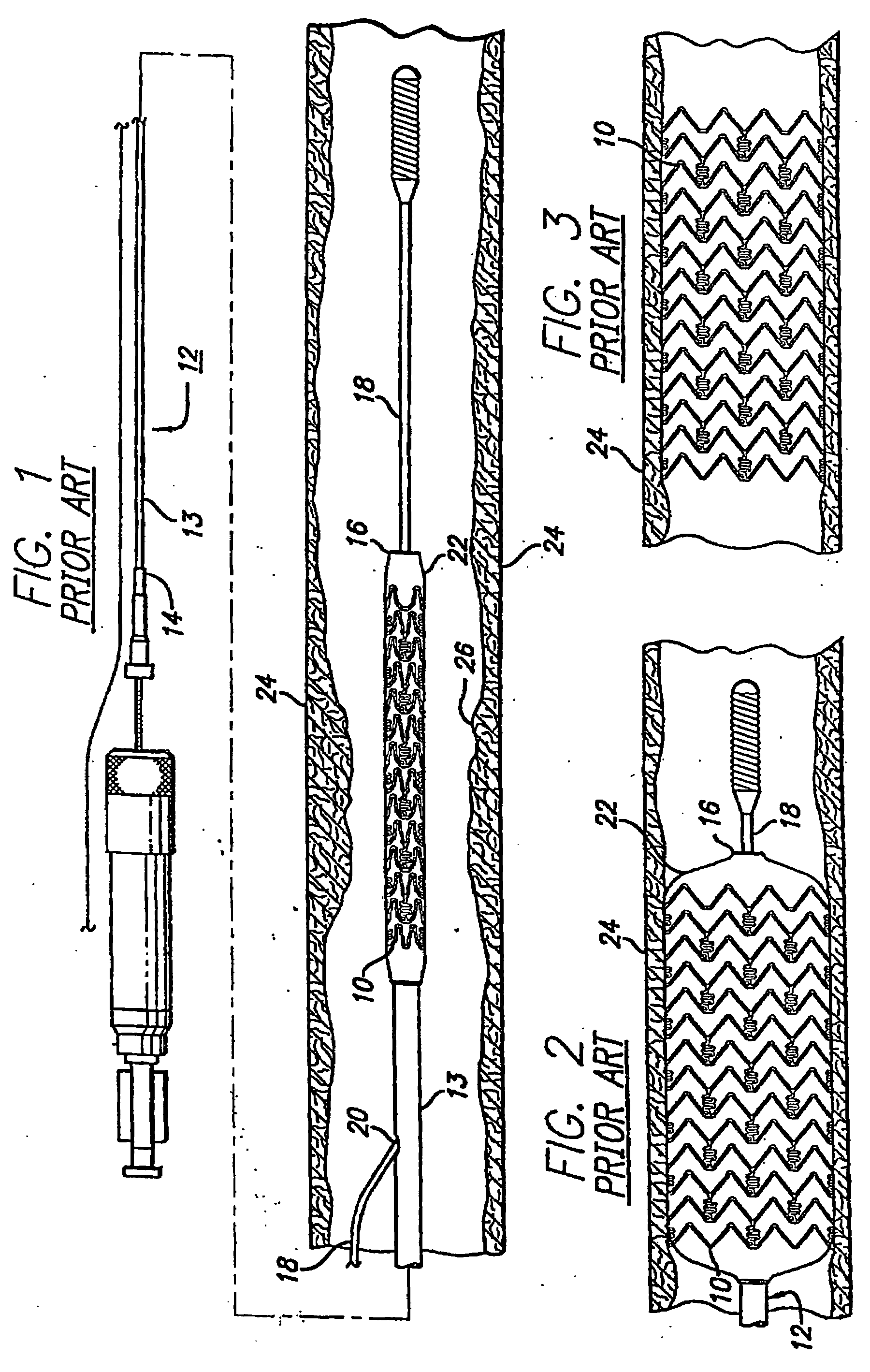
[0039]Turning to the drawings, FIG. 1 depicts a prior art stent 10 mounted on a conventional catheter assembly 12. The assembly 12 is used to deliver and implant the stent in a body lumen, such as a coronary artery, peripheral artery, or other vessel or lumen within the body. The catheter assembly includes a catheter shaft 13 which has a proximal end 14 and a distal end 16. The catheter assembly is configured to advance through the patient's vascular system over a guide wire by any of the well known methods of an over the wire system (not shown) or by a well known rapid exchange catheter system, such as the one shown in FIG. 1.

[0040]Catheter assembly 12 as depicted in FIG. 1 is of the well known rapid exchange type which includes an RX port 20 where the guide wire 18 will exit the catheter. The distal end of the guide wire 18 exits the catheter distal end 16 so that the catheter advances along the guide wire on a section of the catheter between the RX port 20 and the catheter distal...


PUM


Abstract

A stent design reduces the likelihood of contact among structural members when the stent diameter is reduced before insertion into the body. In one approach, an undulating link has a J-shaped profile or has an angled portion on one side at the peak of the link, in order to reduce contact during crimping. The stent may also include structural features that improve such aspects as flexibility, the coatibility of a drug coating onto the stent, flare reduction, stent retention within the body and / or reduction of the minimum diameter of the stent during crimping.

Description

BACKGROUND OF THE INVENTION[0001]The invention relates to vascular repair devices, and in particular intravascular stents, which are adapted to be implanted into a patient's body lumen, such as a blood vessel or coronary artery.[0002]Stents are generally tubular-shaped devices that hold open a segment of a blood vessel or other body lumen such as a coronary artery. They also are suitable to support and hold back a dissected arterial lining that can occlude the fluid passageway. There are many known stents, such as those disclosed in U.S. Pat. No. 6,629,994, entitled “Intravascular Stent” and issued on Oct. 7, 2003, which is incorporated by reference herein.[0003]The prior art stents depicted in FIGS. 1-5 have multiplex cylindrical rings connected by one or more undulating links. While some of these stents are flexible and have the appropriate radial rigidity needed to hold open a vessel or artery, there typically is a tradeoff between flexibility, radial strength, and the ability to...

Claims


Application Information

Patent Timeline
Patent Type & Authority Applications(United States)
IPC IPC(8): A61F2/06
CPCA61F2/91A61F2/915A61F2002/91508A61F2/89A61F2002/91525A61F2002/91533A61F2002/91575A61F2002/91516A61F2002/91541A61F2002/91566
Inventor KREIDLER, MARC S.MILLER, JESSICA P.
Owner ABBOTT CARDIOVASCULAR
Why Eureka
Try Eureka