Photovoltaic array for concentrated solar energy generator

a photovoltaic array and concentrated solar energy technology, applied in the safety of solar heat collectors, pv power plants, lighting and heating apparatus, etc., can solve the problems of limiting the economic advantage of a large array, complex alignment procedures and test fixtures, and excessive heat from the photovoltaic cell. , to achieve the effect of reducing the cost of installation

Inactive Publication Date: 2008-04-17
SCHWARTZMAN ZALMAN
View PDF8 Cites 88 Cited by
  • Summary
  • Abstract
  • Description
  • Claims
  • Application Information

AI Technical Summary

Benefits of technology

[0058] In another embodiment of the present invention, a reflector is concentrating solar radiation on a photovoltaic cell thermally attached to a metallic rod that penetrate through the transparent protective cover and dissipates excessive heat from the photovoltaic cell to the environment. A light weight heat pipe can be used instead of the metallic rod allowing for better heat dissipation with minimal weight and minimal shadowing. The heat pipe according to the present invention is a thin walled metallic pipe, vacuumed and filled with a small amount thermodynamic liquid. The heat pipe is perpendicular to the solar array plane that is kept directed to the sun by the primary servomechanism, thus the shadow by the heat pipe cross section on the reflector is minimal.
[0059] The orientation of

Problems solved by technology

The photovoltaic cell is considered to be the most expensive component of a solar energy converter.
There are several problems with this approach.
First, large metallic structural grids that have enough rigidity and dimensional accuracy are difficult to design and manufacture, which may limit the economic advantage of a large array.
Complex alignment procedures and test fixtures may be required because module alignment can not be carried out with a live system.
Second problem is that sun tracking of large structures cause significant changes in structural forces caused by gravity.
Furthermore, wind load and temperature variation can also cause significant elastic deformations which can not be accounted for, leading to focus inaccuracy and conversion efficiency degradation.
Averaging of several sensors mounted at different locations on the array may yield control instability issues a

Method used


Image

  • Photovoltaic array for concentrated solar energy generator
  • Photovoltaic array for concentrated solar energy generator
  • Photovoltaic array for concentrated solar energy generator

Examples


Embodiment Construction

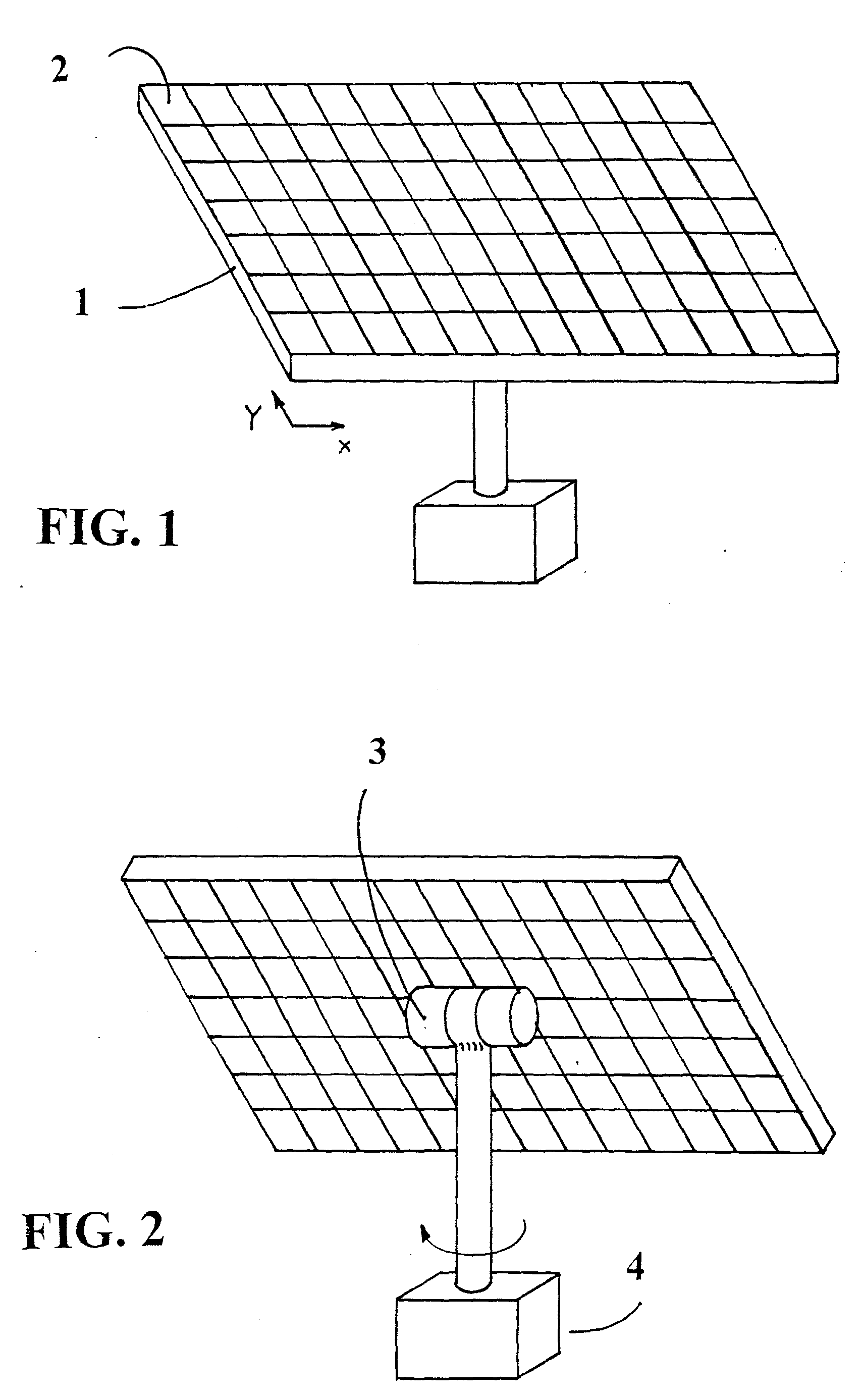
[0075] As illustrated in FIG. 1, a solar energy panel according to the present invention is comprised of a structural grid 1, with multiple power generating modules 2 installed in spaces within said structural grid.

[0076] As can be seen in FIG. 2, The sun tracking panel is positioned by two axis servomechanisms 3&4 to keep the concentrated solar radiation focused on the photovoltaic cells.

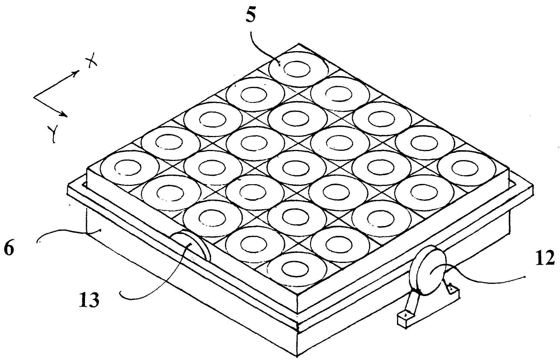
[0077] For each power generating module, the heat sink on which the photovoltaic cell is mounted is exposed to the environment to dissipate excessive heat that is generated by the cell. The heat sink can be formed as a flat plate as showed in FIG. 2 or have fins protruding to the back side of the panel.

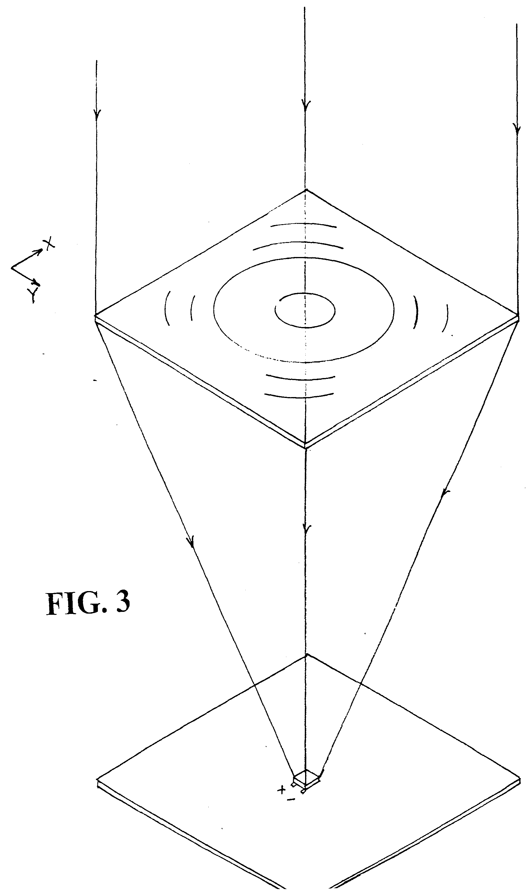
[0078]FIG. 3 shows a Fresnel lens concentrating solar radiation on a square photovoltaic cell mounted on a heat sink plate. The heat sink plate may or may not have fins, and its back side is exposed, dissipating heat to the environment. Electrical connections to the photovoltaic cell are provided,...


PUM

PropertyMeasurementUnit
Fractionaaaaaaaaaa
Angleaaaaaaaaaa
Areaaaaaaaaaaa

Abstract

An extensive photovoltaic array for generating electric power from concentrated solar radiation, formed of an extensive planar structural grid wherein a multitude of power generating modules are installed, said structural grid being positioned by a primary servomechanism to keep incident solar radiation perpendicular to the plane of the array at all times.

Description

FIELD OF THE INVENTION [0001] This invention relates to a photovoltaic power generating module, data communication method between each module and a central controller, module alignment methods, module power conversion and a heat sink for cooling each photovoltaic cell within the module. The module is part of a large concentrated photovoltaic solar energy generator array. BACKGROUND OF THE INVENTION [0002] The invention relates to the generation of photovoltaic electric power from concentrated solar radiation, and more particularly to large sun tracking panels having an array of concentrated photovoltaic power generating modules. See, e.g., U.S. Pat. No. 5,125,983. [0003] Solar energy conversion modules that convert sunlight to electrical power typically employ photovoltaic cells that directly convert sunlight to electrical energy. [0004] Concentrating methods for increasing the solar illumination intensity on photovoltaic cell are usually employed. Such methods include using concent...

Claims


Application Information

Patent Timeline
IPC IPC(8): H01L31/052B29C33/42
CPCF24J2/38F24J2/4625F24J2/542H01L31/0543Y02E10/40H02S20/00Y02E10/52H02S20/30H02S40/22F24S50/20F24S40/55F24S30/452
Inventor SCHWARTZMAN, ZALMAN
Owner SCHWARTZMAN ZALMAN
Why Eureka
Try Eureka