Combination structure of spring power assembly and head rail

a technology of power assembly and combination structure, which is applied in the direction of door/window protective devices, building components, constructions, etc., can solve the problems of power spring damage, no modular design between the spring driver unit and the transmission shaft, and a lot of time and cost must be spent on assembling and maintenance, so as to enhance the convenience of assembling and maintenance

Inactive Publication Date: 2008-04-17
NIEN MADE ENTERPRISE CO LTD
View PDF9 Cites 16 Cited by
  • Summary
  • Abstract
  • Description
  • Claims
  • Application Information

AI Technical Summary

Benefits of technology

[0008]In view of the above problems, the present invention is directed to providing a combination structure of a spring power assembly and a head rail, so as to make the spring power assembly to be modularly designed and achieve the directionality in assembling the spring power assembly with the head rail. Additionally, the spring power assembly has stopping characteristic, so as to enhance the convenience in assembling and maintenance.
[0009]Therefore, the present invention discloses a combination structure of a spring power assembly and a head rail, wherein the spring power assembly is integrated and assembled into the head rail, a revolving shaft of a power spring assembled into the spring power assembly is perpendicular to the direction of a shaft passing through the spring power assembly, thereby reducing the required volume of the spring power assembly. The head rail comprises a front wall, a rear wall, and a connection portion. The front wall and the rear wall are connected via the connection portion to form a fore and aft arrangement, and an accommodation space is formed between the front wall and the rear wall. A first gripping part is formed in the front wall and a second gripping part is formed at the outer edge of the housing of the spring power assembly. When the first gripping part faces the front, the second gripping part stops at one end of the accommodation space to prevent the spring power assembly from entering into the accommodation space.
[0010]Furthermore, in order to assemble the spring power assembly more conveniently, a bayonet pin is used to stop the spring power assembly; thus, the spring power assembly may be kept in an initial state when being assembled. In addition, if the spring power assembly rotates wrongly due to an external force, it may be stopped instantly by using the bayonet pin, so as to reduce the damage to the spring power assembly.
[0011]In view of the above, the combination structure of the spring power assembly and the head rail provided by the present invention makes the spring power assembly be a modular design, and the spring power assembly and the head rail are designed to be unique in assembling, so as to ensure the spring power assembly to be assembled correctly, and thereby preventing the spring power assembly from being damaged due to the wrong assembling direction. Besides that the uniqueness of the assembling method is utilized to prevent the spring power assembly from being damaged, the spring power assembly has a stopping mechanism to stop the spring power assembly timely, and thereby achieving the efficacy of reducing the damage to the spring power assembly.

Problems solved by technology

However, in U.S. Pat. Publication No. 6,283,192, no modular design is provided between the spring driver unit and the transmission shaft.
Therefore, a lot of time and cost must be spent on assembling and maintenance.
However, the spring housing uses the power spring as a power source, therefore, as for the spring housing, the rotation direction of the load and the rotation direction of the recovery of the spring are specified in advance and cannot be alternately used.
If they are alternately used, the power spring will be damaged.
Furthermore, when being assembled by a common user, it may often be assembled incorrectly, and thereby damaging the spring housing.

Method used


Image

  • Combination structure of spring power assembly and head rail
  • Combination structure of spring power assembly and head rail
  • Combination structure of spring power assembly and head rail

Examples


Embodiment Construction

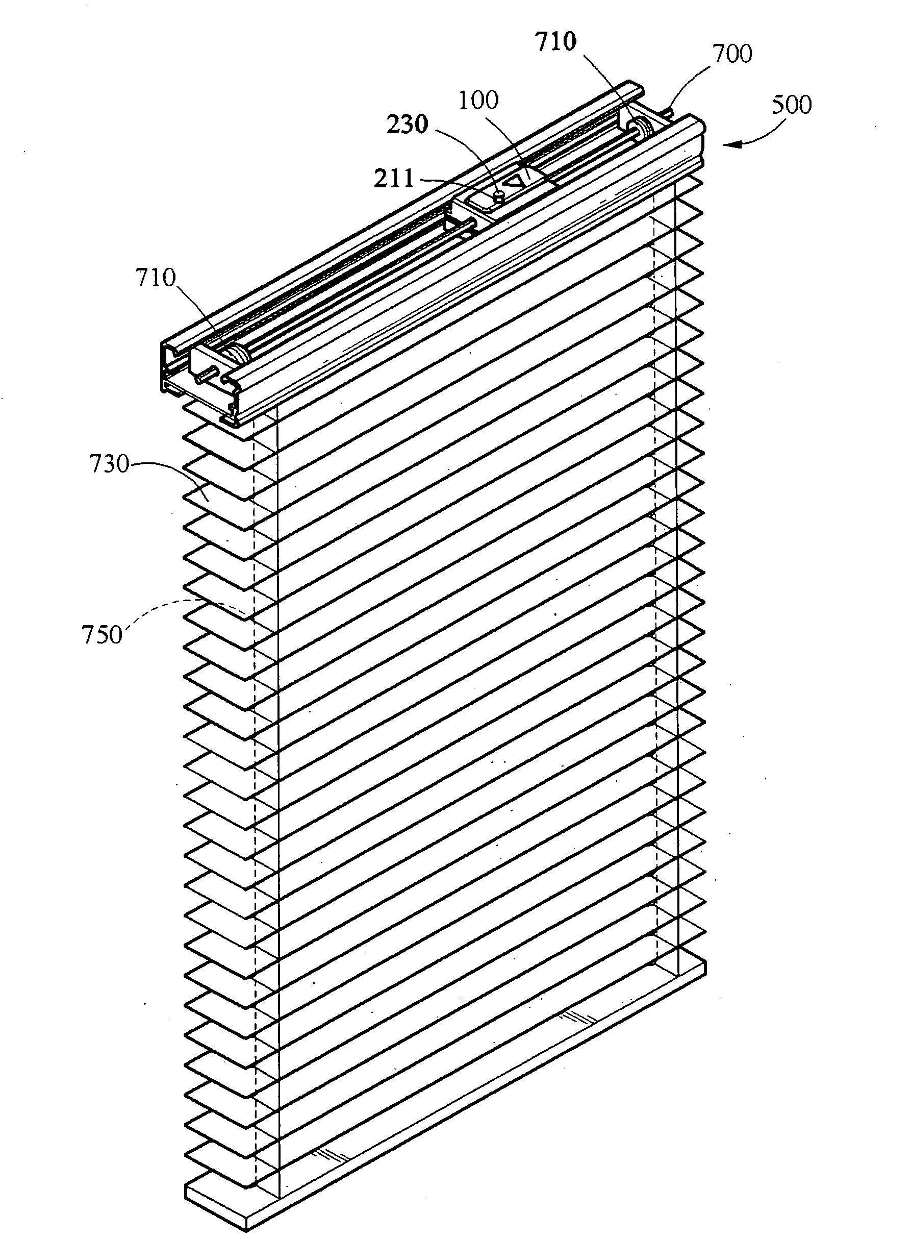
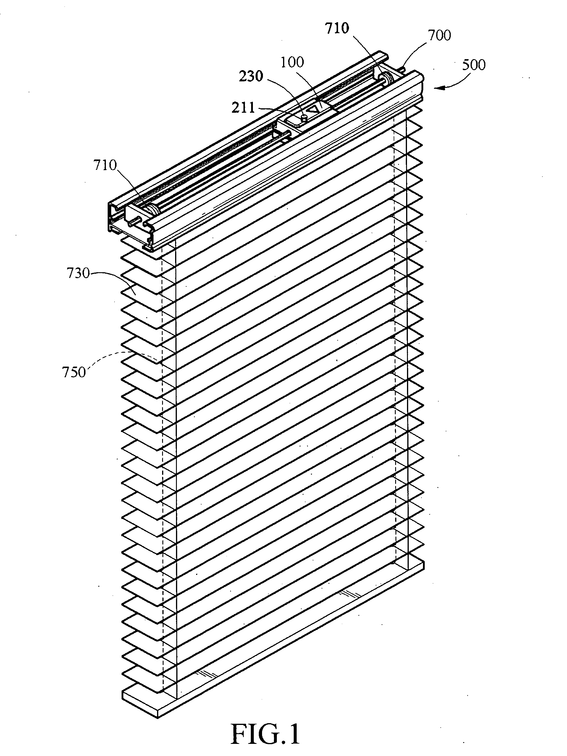
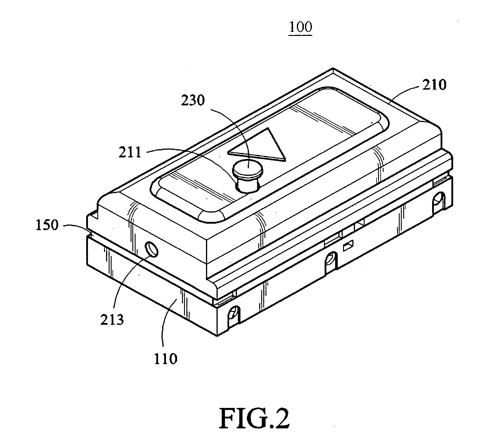
[0022]As shown in FIGS. 1, 2, and 3, they are respectively a schematic assembled view for a spring power assembly of the present invention to be applied in a shutter, a schematic assembled view of the spring power assembly of the present invention, and a schematic exploded view of the spring power assembly of the present invention. A spring power assembly 100 and a cord pulley 710 are assembled in a head rail 500, and a shaft 700 passes through the spring power assembly 100 and the cord pulley 710. The spring power assembly 100 may generate a torsional force to rotate the shaft 700, so as to further drive the cord pulley 710 to rotate and thereby winding a lift cord 750 passing through a plurality of slats 730.

[0023]The spring power assembly 100 includes a housing composed of a base 110, a middle cover 150, and a top cover 210, wherein a power spring 130, a first transmission element, and a second transmission element are assembled into the housing.

[0024]The power spring 130 is disp...


PUM


Abstract

A combination structure of a spring power assembly and a head rail is provided. A revolving shaft of a power spring is made to be perpendicular to a major axis of the head rail, so as to reduce the height of the head rail. The head rail has a first gripping part and the spring power assembly has a second gripping part corresponding to the first gripping part and a bayonet pin, which prevents the spring power assembly from being placed into the head rail along a wrong direction and / or prevents the spring power assembly from rotating along a wrong direction, so as to avoid damages to the spring power assembly caused by errors in the assembling process.

Description

BACKGROUND OF THE INVENTION[0001]1. Field of Invention[0002]The present invention relates to a spring power assembly structure and a combination structure of a spring power assembly and a head rail, and more particularly, to a directionality when the spring power assembly is assembled with the head rail, and a modular structure of the spring power assembly.[0003]2. Related Art[0004]Generally speaking, a cordless shutter structure is driven by a spring housing or an electric motor, and the spring housing is a common means for driving. Related arts, such as U.S. Pat. Publications No. 5,482,100, 5,531,257, and 6,234,236, have disclosed that a spring motor is used as a power source for rotation, and a cord spool is fixed at one side of the spring motor, such that the spring motor directly drives the cord spool to rotate and thereby winding cords.[0005]Additionally, U.S. Pat. Publication No. 6,056,036 has also disclosed that, a spring assembly composed of a power spring is used as a powe...

Claims


Application Information

Patent Timeline
Patent Type & Authority Applications(United States)
IPC IPC(8): E06B9/30
CPCE06B9/322E06B9/60E06B9/368E06B9/323
Inventor NIEN, MINGWEN, YU-CHECHANG, CHIH-YAO
Owner NIEN MADE ENTERPRISE CO LTD
Why Eureka
Try Eureka