Raceway Ring for Radial Ball Bearing and Manufacturing Method Thereof, and Manufacturing Method of High Accurate Ring and Manufacturing Apparatus Thereof

a technology of radial ball bearings and ring rings, which is applied in the direction of bearing components, metal-working apparatus, shafts and bearings, etc., can solve the problems of deterioration of material yield, increased manufacturing costs, and difficulty in determining the size and shape of compound partially finished materials, etc., to achieve low manufacturing cost, low rotation accuracy, and high material accuracy

Inactive Publication Date: 2008-04-17
NSK LTD
View PDF5 Cites 10 Cited by
  • Summary
  • Abstract
  • Description
  • Claims
  • Application Information

AI Technical Summary

Benefits of technology

[0171] According to the raceway ring for a radial ball bearing composed as described above and the manufacturing method thereof of the present invention, a raceway ring composing a radial ball bearing, which is applied to the above use, the rotation accuracy of which is not so high, can be obtained at a low manufacturing cost while the accuracy, which is sufficiently high for practical use, is being maintained.
[0172] A cylindrical material (a high accurate material), the volume of which is the same as that of a raceway ring to be manufactured (In the case where finish working is conducted being accompanied by the removal of the material, consideration is given to it.), is plastically deformed by cold working to form the raceway ring. Therefore, accuracy of the shape and size of this raceway ring can be maintained high.
[0173] Of course, when the accuracy of working is enhanced, the present invention can be applied to a raceway ring for a ball bearing for which high accuracy is required.
[0174] According to the manufacturing method of the above highly accuracy ring of the present invention, it is possible to easily and efficiently manufacture a high accurate ring, the inner diameter, the outer diameter and the size in the axial direction of which are regulated to be proper values, and the central axes of the inner and outer circumferential faces of which strictly agree with each other, by a high yield. As a result, the cost for working an outer ring or an inner ring composing a radial ball bearing, which is made when the high accurate ring is worked, can be reduced while a sufficiently high performance is being maintained for the practical use.
[0175] Of course, when the accuracy of working is enhanced, the present invention can be applied to a high accurate ring used for manufacturing a raceway ring of a ball bearing for which high accuracy is required.

Problems solved by technology

The above manufacturing method of the inner ring is disadvantageous in that the yield of material is deteriorated and further the manufacturing cost is raised.
Therefore, it is difficult that the accuracy of the size and shape of the compound partially finished material and the partially finished material, which is formed out of this compound partially finished material, for making an outer and an inner ring is maintained to be sufficiently high.
Especially when the compound partially finished material, the volume of which is large, is made by means of cold forging, an excessively heavy load is given to the metallic die.
Accordingly, it becomes difficult to ensure the durability of the metallic die.
Therefore, it becomes difficult that the accuracy of the sizes of the outer and the inner diameter of the obtained compound partially finished material are maintained to be sufficiently high.
It also becomes difficult that the accuracy of the size and the shape of the inner and the outer circumferential face is maintained to be sufficiently high.
It also becomes difficult that the accuracy of the concentricity of the inner and the outer circumferential face is maintained to be sufficiently high.
As a result, even when the ball bearing is used for a device in which a high rotary accuracy is not required, it becomes difficult that the dimensional accuracy and the deflection accuracy of the inner and the outer diameter of the inner and the outer ring are maintained to be sufficiently high.
It is impossible to form engaging grooves for engaging outer circumferential edges of sealing plates on both sides of the inner circumferential face of the outer ring by means of plastic working.
Accordingly, it is difficult to sufficiently reduce the manufacturing cost.
Therefore, it is difficult that the size of the inner and the outer diameter of this material is maintained at high accuracy.
Further, it is difficult that the size, shape and concentricity of the inner and the outer circumferential face are maintained at high accuracy.
As a result, the accuracy of the size of the inner and the outer diameter of the obtained outer ring can not be maintained high.
Further, the deflection accuracy of the inner and the outer diameter of the obtained outer ring can not be maintained high.
When the ring-shaped material is made by cutting a steel pipe, it takes time and labor.
Therefore, the productivity is deteriorated, which raises the manufacturing cost.
From this viewpoint, the manufacturing cost is raised.
However, in this conventional method described in Patent Documents 3 and 4, it is difficult to stabilize behavior of the ring-shaped material under the condition that the mandrel is pressed.
Therefore, it is impossible to accurately transfer the shape of the outer circumferential face of the mandrel onto the circumferential face of the ring-shaped material.
Further, it is difficult that the circularity of the thus obtained raceway ring is maintained to be sufficiently high.
Therefore, even when the ball bearing is applied to a use in which a high rotary accuracy is not required, it is difficult to maintain the dimensional accuracy sufficiently high.
Therefore, a reduction of the manufacturing cost is limited.
Accordingly, it is impossible to ensure the accuracy in the axial direction of the thus obtained ring-shaped component.
As a result, it is impossible to ensure the accuracy of the volume.
For the above reasons, it is difficult to manufacture a raceway ring, which can be practically used, only by conducting plastic work on this ring-shaped component.

Method used


Image

  • Raceway Ring for Radial Ball Bearing and Manufacturing Method Thereof, and Manufacturing Method of High Accurate Ring and Manufacturing Apparatus Thereof
  • Raceway Ring for Radial Ball Bearing and Manufacturing Method Thereof, and Manufacturing Method of High Accurate Ring and Manufacturing Apparatus Thereof
  • Raceway Ring for Radial Ball Bearing and Manufacturing Method Thereof, and Manufacturing Method of High Accurate Ring and Manufacturing Apparatus Thereof

Examples


embodiment 1

[0427] First of all, referring to Embodiments 1 to 6, a method of forming an outer ring of the present invention will be explained.

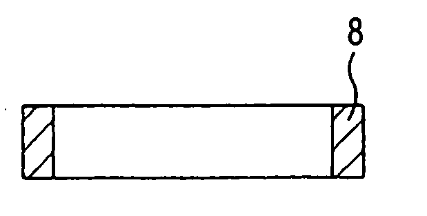
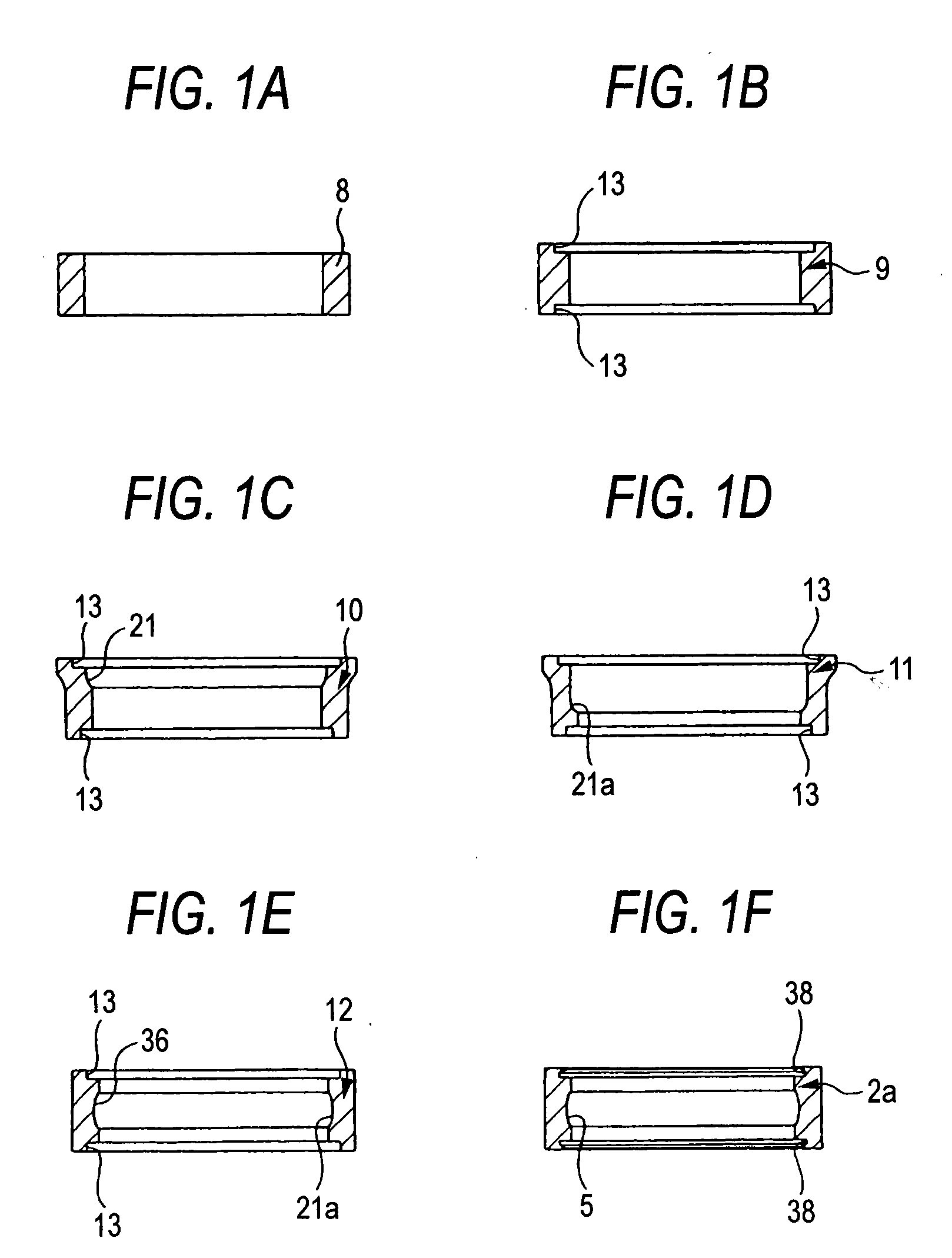
[0428] FIGS. 1 to 6 are views showing Embodiment 1 of the present invention. The present invention is characterized in that: after a cylindrical high accurate material 8 (shown in FIG. 1(A)), the volume of which is substantially the same as that of the outer ring 2a (shown in FIG. 1(F)), is previously made, this cylindrical high accurate material 8 is plastically deformed by means of cold working so that it can be formed into the outer ring 2a. The method of making this high accurate material 8 is not particularly limited to a specific method. However, from the viewpoint of enhancing the yield of material and reducing the manufacturing cost, it is preferable to manufacture high accurate material 8 in such a manner that a long wire rod (wire coil) is cut into a predetermined length and subjected to cold plastic working. Alternatively, when a plate member...

embodiment 2

[0442] According to the method of the second embodiment shown in FIG. 6, rolling is conducted in such a manner that the third partially finished material 12 is pressed from both sides in the radial direction between an inner circumferential face of the outer roller 39 and an outer circumferential face of the inner roller 40, wherein the outer roller 39 and the inner roller 40 are arranged eccentrically to each other and rotated in the same direction. An inner circumferential face of the outer roller 39 is formed out of a simple cylindrical face and supports an outer circumferential face of the third partially finished material 12. On the other hand, a shape of the cross-section of axially intermediate portion of the outer circumferential face of the inner roller 40 is made to agree with the shape of the cross-section of the inner circumferential face of the outer ring 2a to be manufactured. In the case of the present embodiment, the third partially finished material 12 is interposed...

embodiment 3

[0445]FIGS. 7 and 8 are views showing Embodiment 3 of the present invention. In the present embodiment, raceway forming and sealing face forming, which are the fourth and the fifth process in Embodiment 1, are simultaneously conducted by rolling. That is, the secondary partially finished material 11 shown in FIG. 1(D) described before is worked into the outer ring 2a shown in FIG. 1(F) without being subjected to the process shown in FIG. 1(E). Therefore, a circumscribing roller 129a composing the rolling device is formed into an annular shape. Inside this circumscribing roller 129a, an inscribing roller 130 is inserted under the condition that both the rotary central axes are arranged in parallel with each other and under the condition that both the rotary central axes are eccentric to each other. When rolling is conducted in which the secondary partially finished material 11 is worked into the outer ring 2a, the inscribing roller 130 is rotated being pressed onto the inner circumfe...


PUM

PropertyMeasurementUnit
inclination angleaaaaaaaaaa
angleaaaaaaaaaa

Abstract

A manufacturing method of a raceway ring for a radial ball bearing, the radial ball bearing has the raceway ring has at least one of an outer ring formed with an outer ring raceway, of which sectional shape is arcuate, and which is formed entire of circumference on an axially intermediate portion of an inner circumferential face as a raceway surface; and an inner ring formed with an inner ring raceway, of which sectional shape is arcuate, and which is formed entire of circumference on an axially intermediate portion of an outer circumferential face as the raceway surface and plurality of balls rollably provided between the inner ring raceway and the outer ring raceway. The manufacturing method of the raceway ring has a high accurate material working process of preparing a high accurate material of which volume is substantially the same as that of the raceway ring of the radial ball bearing which is a finished product by cold working and a raceway ring working process of plastically deforming the high accurate material by cold working and forming the raceway surface on the axially intermediate portion of either outer or inner circumferential face wherein working for removing material is not conducted before a heat treatment.

Description

TECHNICAL FIELD [0001] The present invention relates to a raceway ring composing a radial ball bearing, in which a rotating accuracy is not required to be so high. Such the radial ball bearing is incorporated into a rotary supporting portion of an electric motor, which is assembled to various electric appliances such as a vacuum cleaner, a ventilating fan and so forth, or incorporated into a rotary supporting portion of various auxiliary machines for automobile use. The present invention also relates to an improvement in the manufacturing method of the raceway ring. BACKGROUND ART [0002] Into rotary supporting portions of various rotary devices, a radial ball bearing 1 shown in FIG. 53 is incorporated. This radial ball bearing 1 is a deep groove type ball bearing, in which a plurality of balls 4, 4 are provided between an outer ring 2 and an inner ring 3 which are arranged concentrically to each other. In this ball bearing, an outer ring raceway 5 of the deep groove type is formed i...

Claims


Application Information

Patent Timeline
Patent Type & Authority Applications(United States)
IPC IPC(8): F16C33/58B21J5/00B21K1/04
CPCB21H1/12B21K1/04Y10T29/49689F16C19/06F16C33/64B23P15/003
Inventor KOBAYASHI, KAZUTOOOTSUKA, KIYOSHISHINTOU, ISAOMORI, KOUHEIYASUDA, YU
Owner NSK LTD
Why Eureka
Try Eureka