Heat treatment apparatus

a technology of heat treatment apparatus and heating chamber, which is applied in lighting and heating apparatus, furnace types, furnaces, etc., can solve the problems of metal contamination of wafers, affecting the heating effect, and causing damage, so as to prevent direct contact, reduce pressure, and prevent damage

Active Publication Date: 2008-04-17
TOKYO ELECTRON LTD
View PDF15 Cites 20 Cited by
  • Summary
  • Abstract
  • Description
  • Claims
  • Application Information

AI Technical Summary

Benefits of technology

[0007]The present invention has been made in view of the foregoing problems, and therefore the object of the invention is to provide a heat treatment apparatus capable of preventing direct contact between a lid and a furnace throat or a furnace throat member due to squashing of a sealing member disposed therebetween under reduced pressure, and of preventing damage, such as cracking, of the furnace throat, or chafing between the lid and the throat member.
[0012]According to the present invention, direct contact between the lid and the furnace throat due to the squashing of the sealing member between the lid and the throat under reduced pressure can be prevented. Thus, damage, such as cracking, of the furnace throat can be prevented, resulting in a longer working life of the processing vessel. In addition, chafing between the lid and the throat member can be prevented, and thus metallic contamination of the process objects due to the chafing can be prevented.
[0013]Preferably, the contact-preventing member has an annular shape and has a cutout to absorb circumferential thermal expansion of the contact-preventing member. Due to the annular configuration, the compressive load exerted on the contact-preventing member is distributed so that the contact-preventing member can withstand the compressive load; and due to the provision of the cutout, the circumferential thermal expansion of the contact-preventing member can be well absorbed. Thereby, a longer life of the contact-preventing member and the processing vessel can be achieved.
[0014]Preferably, an engagement projection, for preventing disengagement of the contact-preventing member from the lid, is formed at a lower portion of the contact-preventing member, the engagement projection extends circumferentially, and the engagement projection has a downward projecting part and a radially outward projecting part projecting from the downward projecting part; and an annular engagement groove, with which the engagement projection is detachably engaged, is formed at an upper portion of the lid. Due to the above structure, the contact-preventing member can be easily installed on the upper portion of the lid, and unexpected disengagement of the contact-preventing member from the upper portion of the lid can be prevented. In addition, the contact-preventing member can be easily removed from the lid by compressing the contact-preventing member to be in a reduced diameter and then by raising the contact-preventing member by hand work. Thus, the contact-preventing member can be easily replaced with a new one, resulting in improved maintainability.
[0015]Preferably, a disengagement-preventing member is attached to an outer side of the lid, and the disengagement-preventing member engages with an engagement groove formed in an outer side of the contact-preventing member to prevent the contact-preventing member from being removed from the lid. Thereby, unexpected disengagement of the contact-preventing member from the upper section of the lid due to any external force can be prevented with further certainty.
[0016]Preferably, the contact-preventing member has an annular shape and has a cutout to absorb circumferential thermal expansion of the contact-preventing member; a stepped portion is formed on a peripheral portion of the lid outside the sealing member, the contact-preventing member engages with the stepped portion, an upward-disengagement preventing structure for preventing upward movement of the contact-preventing member is provided on an outer circumferential surface of the stepped portion and on an inner circumferential surface of the contact-preventing member; and a plurality of expansion-preventing members are provided on an outer circumferential surface of the lid at intervals to suppress outward expansion of the contact-preventing member. Thereby, the contact-preventing member is formed into a simple shape avoiding stress concentration, and a wide pressure-bearing area of the contact-preventing member is ensured.

Problems solved by technology

Due to this, contact pressure is exerted on the furnace throat 2a, resulting in damage of the furnace throat 2a such as cracking, and generation of particles due to micro cracks.
This causes chafing between the lid 15 and the manifold 50 due to difference in their thermal expansions, resulting in metallic contamination of wafers.

Method used


Image

  • Heat treatment apparatus
  • Heat treatment apparatus
  • Heat treatment apparatus

Examples


first embodiment

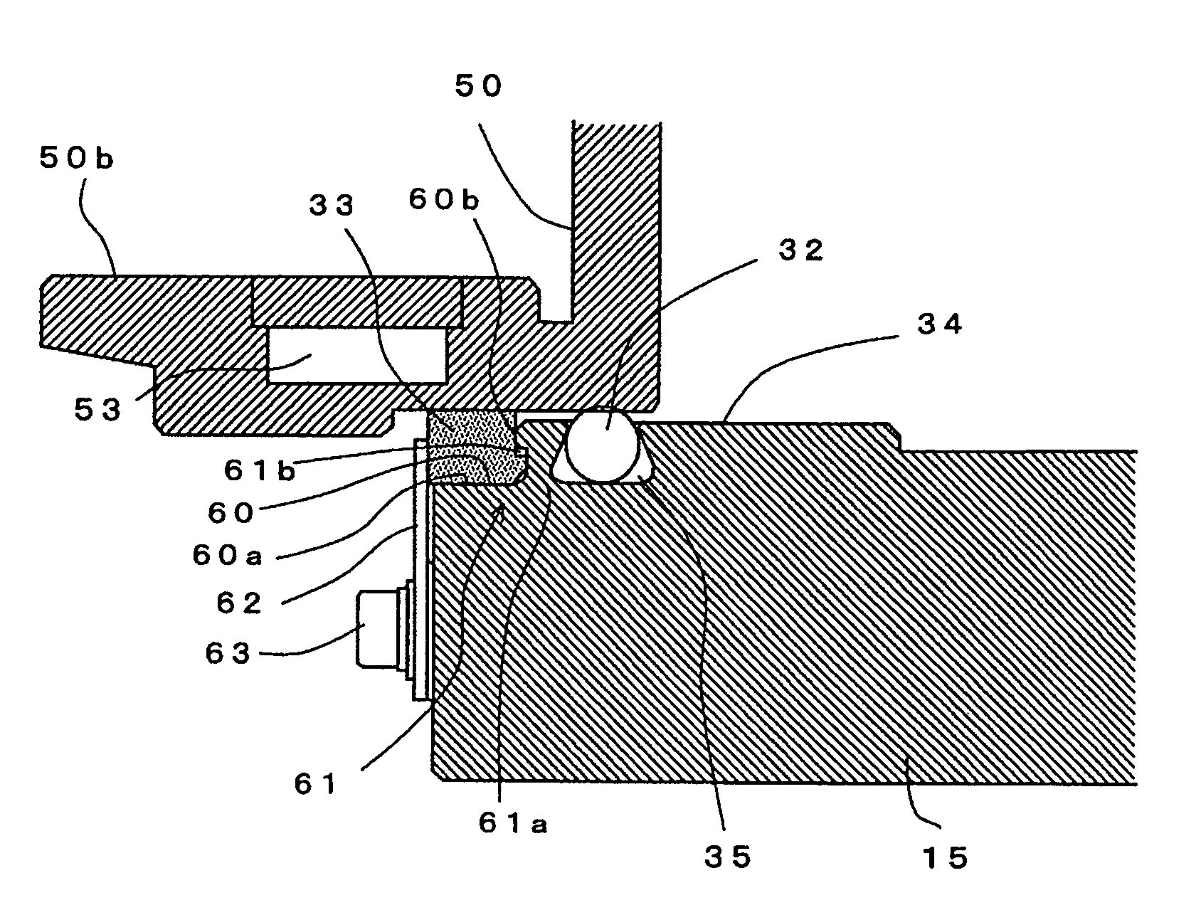
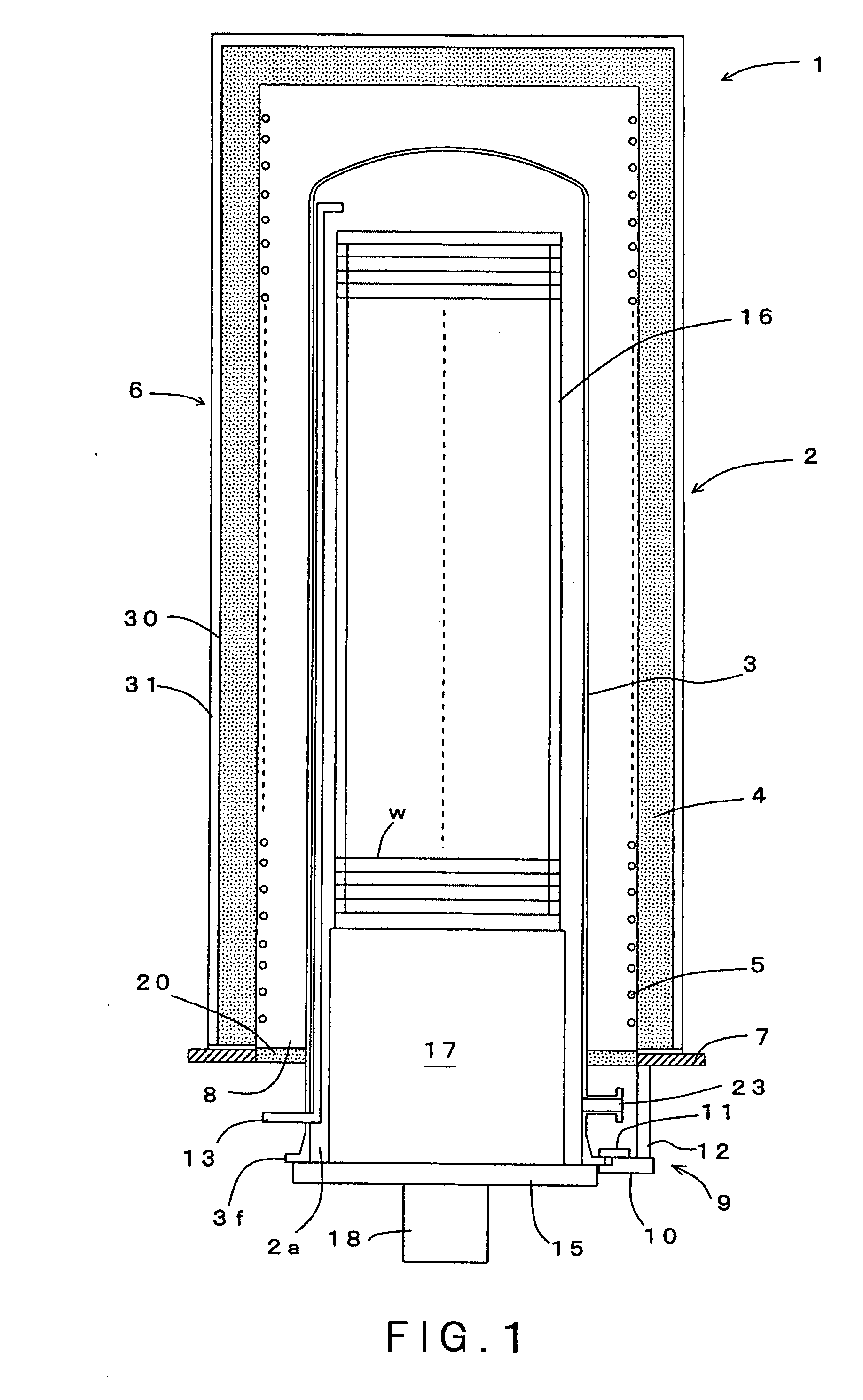
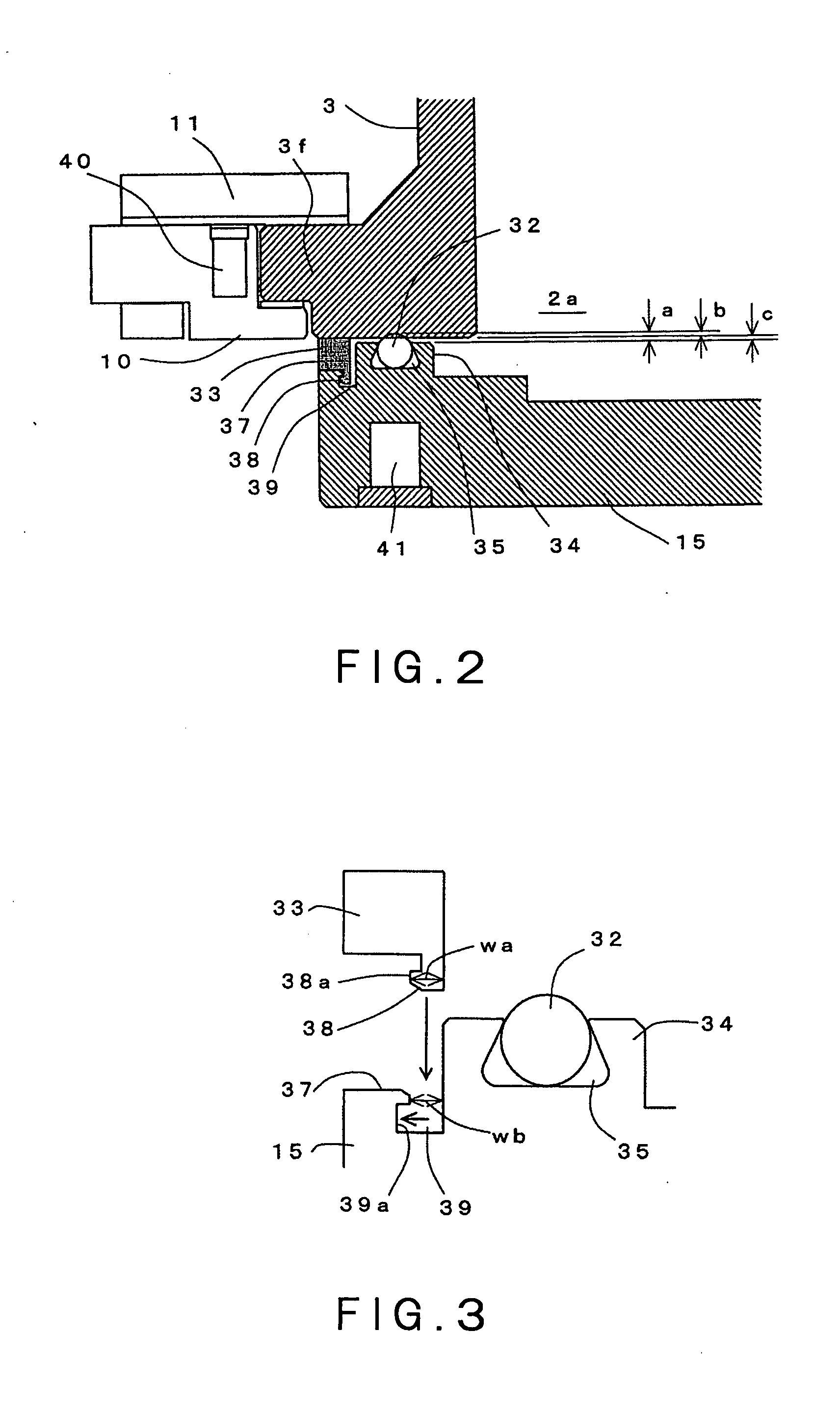
[0031]Preferred embodiments of the present invention will be described in detail with reference to the accompanying drawings. FIG. 1 is a vertical cross-sectional view schematically showing a heat treatment apparatus in the present invention. FIG. 2 is an enlarged cross-sectional view showing a main portion of the heat treatment apparatus. FIG. 3 is a diagram explaining a structure for mounting a contact-preventing member on a lid. FIG. 4 is a plan view of the contact-preventing member.

[0032]Referring to FIG. 1, reference number 1 denotes a vertical heat treatment apparatus that is one type of semiconductor manufacturing apparatus. The heat treatment apparatus 1 has a vertical heat treatment furnace 2, which is adapted to accommodate simultaneously a large number of process objects, such as semiconductor wafers W, so as to perform a heat treatment (thermal process) such as low-pressure diffusion process to those wafers. The heat treatment furnace 2 primarily includes: a processing v...

second embodiment

[0054]FIG. 9 is a vertical cross-sectional view schematically showing a heat treatment apparatus in the present invention. FIG. 10 is an enlarged cross-sectional view showing main parts of the heat treatment apparatus. In FIG. 9, reference number 1 denotes a vertical heat treatment apparatus that is one type of semiconductor manufacturing apparatus. The heat treatment apparatus 1 has a vertical heat treatment furnace 2, which is adapted to accommodate simultaneously a large number of process objects, such as semiconductor wafers W, so as to perform a heat treatment (thermal process) such as low-pressure diffusion process to those wafers. The heat treatment furnace 2 primarily includes: a processing vessel (a vessel main body) 3 that accommodates the wafers W at multiple levels to perform a predetermined heat treatment to the wafers W; and a heater 6 surrounding the processing vessel 3 to heat the wafers W.

[0055]The heat treatment apparatus 1 has a base plate 7 for installing the hea...


PUM


Abstract

Disclosed is a heat treatment apparatus which includes a processing vessel having a furnace throat at its bottom and adapted to accommodate process objects therein to perform a heat treatment to the process objects under reduced pressure, the processing vessel having a vessel main body made of quartz, a metallic lid adapted to support thereon a holder for holding a plurality of process objects so as to load and unload the holder into and from the processing vessel and to close and open the furnace throat, and an annular sealing member disposed on the lid to seal a gap between the lid and the furnace throat. A contact-preventing member is disposed between the lid and the furnace throat to prevent contact of the lid with the furnace throat due to squashing of the sealing member that would otherwise occur when an internal pressure of the processing vessel is reduced.

Description

TECHNICAL FIELD[0001]The present invention relates to a heat treatment apparatus.BACKGROUND ART[0002]In manufacturing of semiconductor devices, various processing apparatuses (semiconductor-manufacturing apparatuses) are used to perform various processes, such as oxidizing, diffusing and CVD (Chemical Vapor Deposition), to process objects, such as semiconductor wafers (hereinafter, also referred to simply as “wafers”). As one type of such processing apparatuses, there has been known a batch-type heat treatment apparatus (e.g., a vertical heat treatment apparatus) that performs a heat treatment (thermal process) to a large number of wafers at a time (refer to JP2001-237238A, for example).[0003]One example of the vertical heat treatment apparatus is a low-pressure diffusion apparatus, part of which is shown in FIG. 13. The low-pressure diffusion apparatus of FIG. 13 includes: a processing vessel 3 (process tube) made of quartz that accommodates wafers therein to perform a heat treatme...

Claims


Application Information

Patent Timeline
Patent Type & Authority Applications(United States)
IPC IPC(8): F27D1/18
CPCF27D99/0073F27B17/0025H01L21/324
Inventor TAKAHASHI, KIICHISASE, YUICHIROSATO, IZUMITAKAHASHI, KIYOHIKO
Owner TOKYO ELECTRON LTD
Why Eureka
Try Eureka