
High powered vehicles replacing the flywheel with the fan

a technology of high-power vehicles and fans, which is applied in the direction of engine controllers, engine cooling devices, engine motor cars, etc., can solve the problems of heavy fuel consumption of engine motor cars, and achieve the effect of damping out torque variations and less fuel consumption

Inactive Publication Date: 2008-04-24
TOMOYASU YOSHIOKI
View PDF2 Cites 3 Cited by
  • Summary
  • Abstract
  • Description
  • Claims
  • Application Information

AI Technical Summary

Benefits of technology

[0004]The invention is generally directed to develop for the high powered engine motor cars with less consumption of the fuels as well as vibration than those of any other conventional vehicles by means of substituting the flywheel which is fitted to the crankshaft to damp out the variations of torque caused by the pistons and reducing the number of the cylinder strokes of the engines for the ducted fan installed in a front position on a shaft of the engine directly connected with the rotating operation of the crankshaft of the engine of the motor cars.
[0005]It is due to the reason why said fan enclosed in the duct with brim serve to augment the rotating force on the blades of the fan continuously capable of driving the vehicle smoothly even if the longer intervals among the combustion operated in the respective engine strokes may be kept in the absence of the function of the flywheel, as if the propeller driven aircraft is not suffered from vertical vibration despite fewer engine cylinder strokes. Thus, the passengers of the vehicles feel high luxurious feeling in the driving operation in the absence of the flywheel of which weight is required for heavy load in view of the functional objective. Thus, considerable saving for fuels as well as comfortable mind for drivers is available.

Problems solved by technology

The heavy fuel consumption of the engine motor cars in the driving operation is partially caused with the flywheel which is fitted to the crankshaft to damp out the variations of the torque imparted by the pistons of the engines and which requires appropriate weight entailing heavy fuel consumption enough to produce the centrifugal force serving to level out the fluctuation of the torque produced in the running operation of the engine motor cars.

Method used


Image

  • High powered vehicles replacing the flywheel with the fan
  • High powered vehicles replacing the flywheel with the fan

Examples


Embodiment Construction

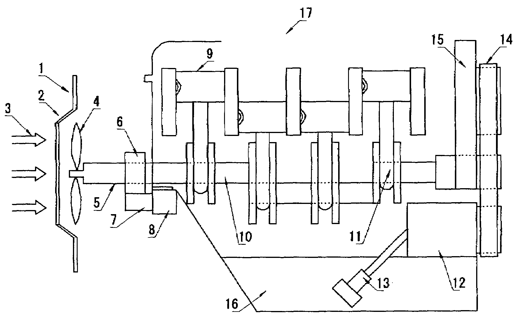
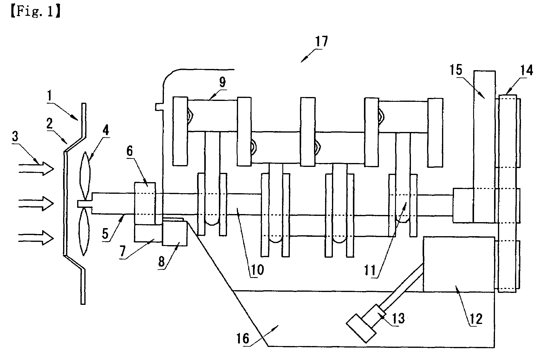
[0008]As shown FIG. 1, the present invention is directed to developing for the high powered vehicle with less consumption of fuels as well as smaller vertical vibration caused by the piston (9) operation in the engine than those of the conventional motor cars by means of substituting the flywheel for the ducted fan (4) installed in the front position on the shaft (5) with the ring gear (6) partially processed on its surface converting the head wind (3) into the kinetic energy to directly assist the continuous rotating operation connected with the operation of the crankshaft (10) of said engine (17) where the pressure difference between the wind flow before and after the brim (1) of the duct (2) cause the attractive force to boost the rotating power in the multiplication for the blades of said fan (4). The engine consists of the starter gear (7), the starter motor (8), the pistons (9), the crankshaft (10), the connecting rods (11), the alternator (12), the oil filter (13), the chille...


PUM


Abstract

The invention is directed to develop for the high power by means of replacing the flywheel with the ducted fan installed in the front position to convert into the rotating force of said fan connected with the rotating operation of the crankshaft of the engine with the strong force enough to reduce the number of the cylinder in the engine while keeping the driving force as well as the stable condition remain as unchanged.

Description

FIELD OF THE INVENTION[0001]The present invention is generally directed to developing for the more comfortable engine motor cars with less fuel consumption in the driving operation and with less expensive in the production costs than those of the conventional vehicles.BACKGROUND OF THE INVENTION[0002]The restriction on the exhausting gases caused by the driving operation of the vehicles is liable to be strictly imposed lately in anywhere on the global markets in view of the heavy air pollution as well as considerable consumption for fuels. Thus it is necessary for further development for basically improving both design and mechanism of the engine motor cars.DESCRIPTION OF THE PRIOR ART[0003]The heavy fuel consumption of the engine motor cars in the driving operation is partially caused with the flywheel which is fitted to the crankshaft to damp out the variations of the torque imparted by the pistons of the engines and which requires appropriate weight entailing heavy fuel consumpti...

Claims


Application Information

Patent Timeline
Patent Type & Authority Applications(United States)
IPC IPC(8): F01P5/10F02B75/06F02D17/02
CPCF01P5/04F02D17/02F02B75/06F02B73/00
Inventor TOMOYASU, YOSHIOKI
Owner TOMOYASU YOSHIOKI
Learn More