Thermodynamic pressure generator

a generator and thermodynamic technology, applied in the field of turbine engines, can solve the problems of near ambient temperature, release of exhaust gases into the atmosphere that are not combustible, etc., and achieve the effects of less fuel consumption, high horsepower, and great torqu

Inactive Publication Date: 2006-02-02
TAFOYA SAMUEL BARRAN
View PDF4 Cites 1 Cited by
  • Summary
  • Abstract
  • Description
  • Claims
  • Application Information

AI Technical Summary

Benefits of technology

[0006] The primary object of this invention is to provide a lightweight and compact thermodynamic rotary power pressure generator of high horsepower and great torque that would allow vehicles to accelerate with less fuel consumption. It is a further object of this invention to produce cost effective and efficient rotary power, while providing a very clean exhaust by incorporating an excess air to fuel mixture. A further object of this invention is to provide a turbine engine that has fewer components than conventional turbine engines and is therefore more durable, more economical to build, simpler to manufacture, and simpler to maintain and repair. It is also an object of this invention to provide a turbine engine that operates with near total combustion, thereby reducing exhaust heat and cooling heat as an energy loss. A further object of this invention is to provide a turbine engine that releases exhaust gases to the atmosphere that are at near ambient temperature and not combustible. It is also an object of this invention to provide a turbine engine that eliminates many of the parts / accessories required by conventional engines. It is a further object of this invention to provide a turbine engine with blades / vanes that rotate at lower speeds to eliminate the explosion risk inherent in high-speed turbine blade rotation. It is also an object of this invention to provide a turbine engine that is able to operate with a currently available standard automatic or manual transmission. It is a further object of this invention to provide a turbine engine that is able to operate with currently available starters, as well as conventional fuels and lubricants.
[0007] As described herein, properly manufactured and used, the present invention is a cost efficient turbine engine that depletes energy resources at a much lower rate than conventional turbine engines and also has a clean exhaust that creates much less an of impact on the environment. The rotor assembly of the present invention turbine engine is typically larger than those used in prior art turbine engines, allowing for a significantly reduced explosion risk since it can generate the torque it needs from a lower rotor assembly speed. Also, a lean fuel / air charge is used in the present invention turbine engine, and the Karmen vortex rings formed by two annular spoilers maintain a portion of the fuel / air charge in laminar to allow for delayed combustion of a portion of the original fuel / air charge that supercharges the remainder of the charge that is already burning in the combustion chamber to create a pulsating type of action that in the excess air to fuel charge environment permits near total combustion of the fuel / air mixture. The supercharging / pulsating combustion creates high horsepower so that land transportation vehicles, propeller-driven airplanes, and marine vessels are able to operate with less fuel consumption. The excess air to fuel charge and near total combustion creates a very clean exhaust, which in part contributes to a need for fewer components than conventional turbine engines and leads to simpler manufacture, maintenance, and repair. Cooling chambers positioned adjacent to the oil reservoir, and oil cooling fins, reduce exhaust heat and cooling heat as an energy loss, resulting in the release of exhaust gases to the atmosphere that are not combustible and near ambient temperature. It is an important difference between the present invention and conventional turbine engines that the exhaust gases of the present invention engine have substantially reduced emissions, are not combustible, and are returned to the atmosphere at near ambient temperature. The present invention is also cost efficient to operate as a result of the fact that it requires no special transmission, starter, fuel, or lubricant, and instead is able to work with standard products that are easily available.

Problems solved by technology

Cooling chambers positioned adjacent to the oil reservoir, and oil cooling fins, reduce exhaust heat and cooling heat as an energy loss, resulting in the release of exhaust gases to the atmosphere that are not combustible and near ambient temperature.

Method used


Image

  • Thermodynamic pressure generator
  • Thermodynamic pressure generator
  • Thermodynamic pressure generator

Examples


Embodiment Construction

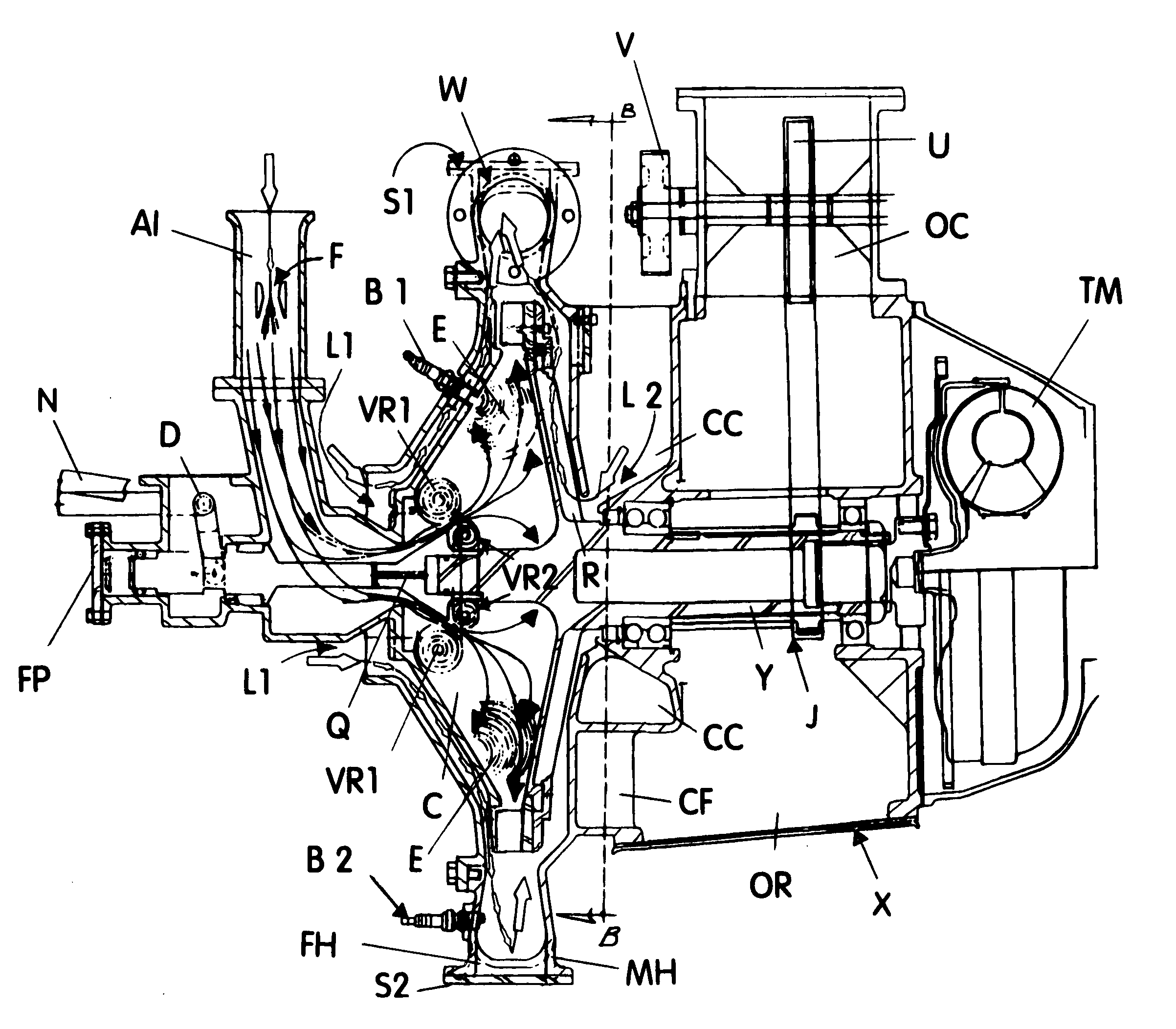
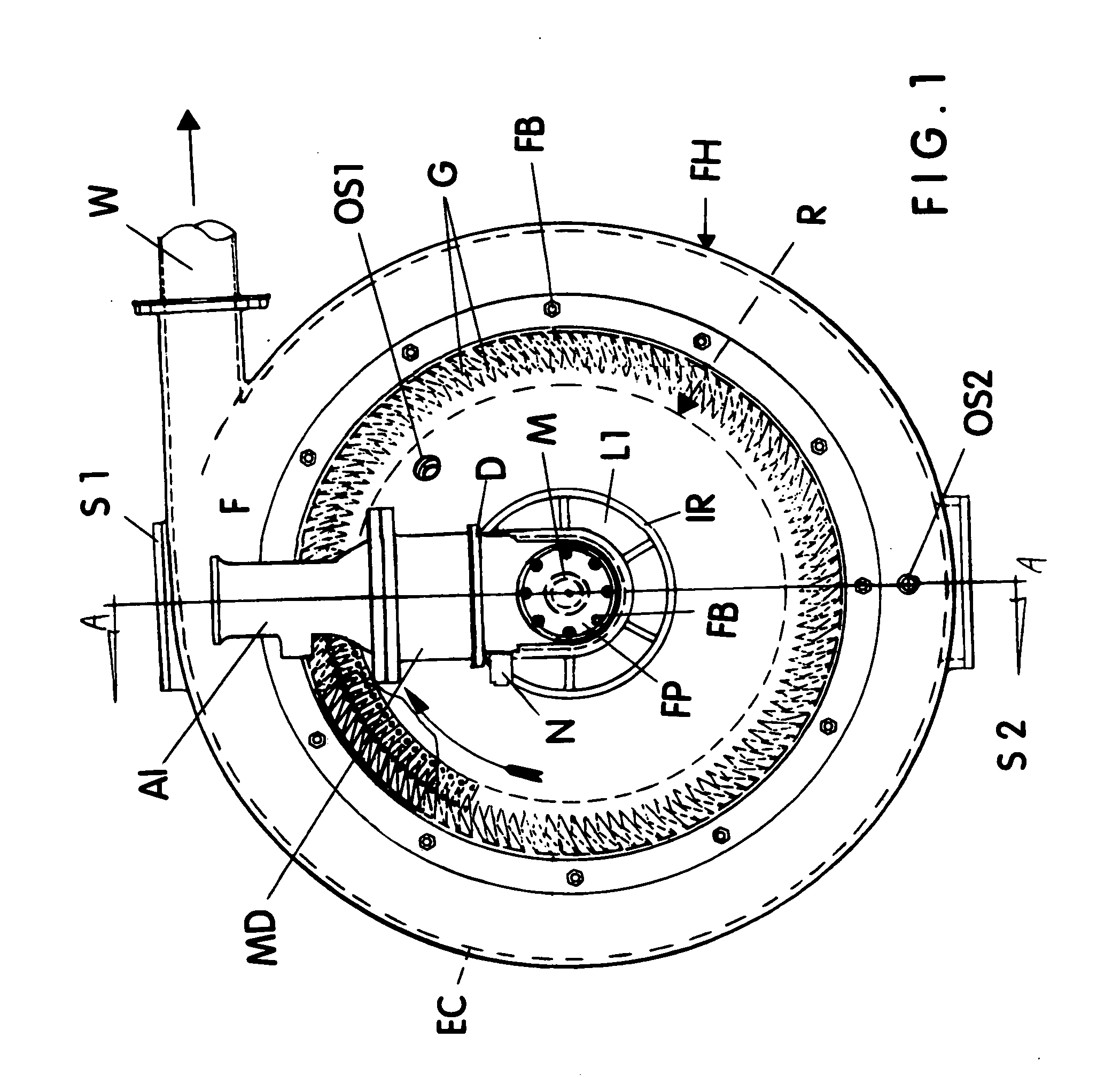
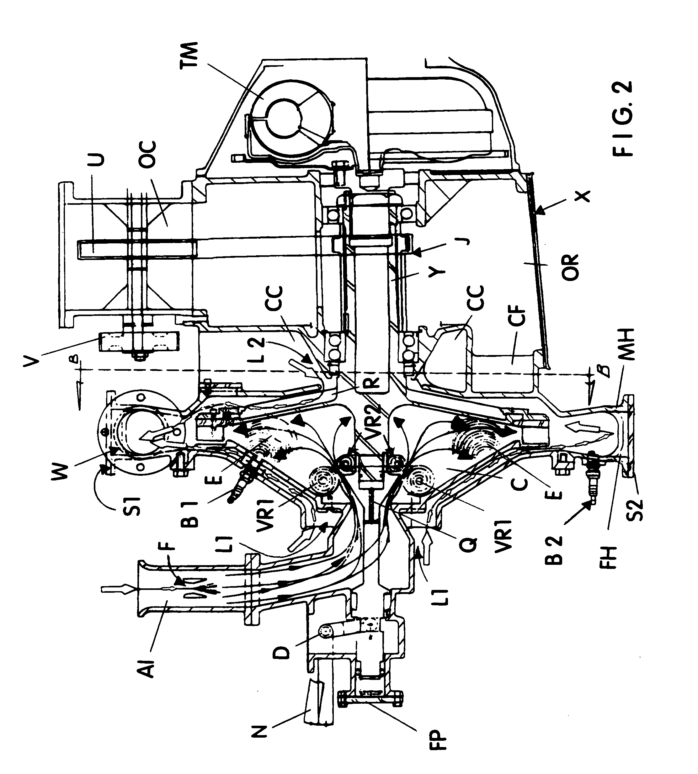
[0017]FIGS. 1-3 show the most preferred embodiment of the present invention turbine engine having an oscillating valve M that allows a premixed fuel mixture (fuel mixture flow is shown by the arrows with solid arrowheads in FIG. 2) to enter a combustion chamber C in turbulence, until it comes into contact with the lips of two annular spoilers A1 and A2, which then convert a portion of the fuel / air mixture into laminar flow in the form of two Karmon vortex rings VR1 and VR2, for delayed ignition. When the remaining turbulent flow is ignited by a continuous spark from igniter B1, a rapid pressure rise occurs that simultaneously kills both vortex rings VR1 and VR2, and the fuel mixture therein goes from laminar to turbulence, adding fuel to the already burning charge E to supercharge it and permit near total ignition. Thus the exhaust gases of the present invention contain no combustible or environmentally polluting by-products. In addition, since the present invention turbine engine a...


PUM


Abstract

A thermodynamic pressure generator having an oscillating valve that allows premixed fuel to enter a combustion chamber in turbulence, until it comes into contact with an annular spoiler, which converts a portion of the fuel into a Karmon vortex ring for delayed ignition. A continuous spark then ignites the remaining fuel with rapid pressure rise that kills the vortex. The fuel in the vortex goes from laminar to turbulence, adding fuel to the already burning charge, super charging it and permitting total ignition. Thus, present invention exhaust contains no polluting by-products and only sensible heat is released into the environment. Exhaust gases are released radially through turbine vanes having a shape that permits a relatively low rotational speed, with sufficient peripheral speed to create torque of considerable degree. Applications include, but are not limited to, land transportation vehicles, propeller-driven airplanes, and marine vessels.

Description

CROSS-REFERENCE TO RELATED APPLICATIONS [0001] None BACKGROUND OF THE INVENTION [0002] 1. Field of the Invention [0003] This invention relates to the field of turbine engines, specifically to a thermodynamic pressure generator that has an oscillating valve allowing a premixed fuel charge to enter a combustion chamber in turbulence, until it comes into contact with two annular spoilers that convert a portion of the mixture into two Karmon vortex rings having laminar flow for delayed ignition. A continuous spark ignites the turbulent air / fuel mixture with rapid pressure rise that kills the formation of the vortex rings. The fuel mixture in the rings then goes from laminar to turbulence, adding fuel to the already burning charge, super charging it and permitting near total ignition. Thus, exhaust from the present invention contains no combustible gases or environmentally polluting by-products. The engine also provides its own cooling system, therefore releasing only sensible heat into ...

Claims


Application Information

Patent Timeline
Patent Type & Authority Applications(United States)
IPC IPC(8): F02C3/16
CPCF01D15/02F02C5/12F02C5/02F02C3/16
Inventor TAFOYA, SAMUEL BARRAN
Owner TAFOYA SAMUEL BARRAN
Why Eureka
Try Eureka