Combustion engine with a priming pump

Inactive Publication Date: 2008-04-24
KAWASAKI HEAVY IND LTD
View PDF4 Cites 5 Cited by
  • Summary
  • Abstract
  • Description
  • Claims
  • Application Information

AI Technical Summary

Benefits of technology

[0006]In view of the foregoing, the present invention is intended to provide a combustion engine e

Problems solved by technology

It has, however, been found that the provision of the insulator structure results in a considerable increase of the size.
However, since the air cleaner hou

Method used


Image

  • Combustion engine with a priming pump
  • Combustion engine with a priming pump
  • Combustion engine with a priming pump

Examples


Embodiment Construction

[0021]Hereinafter, a preferred embodiment of the present invention will be described in detail with particular reference to FIGS. 1 to 3.

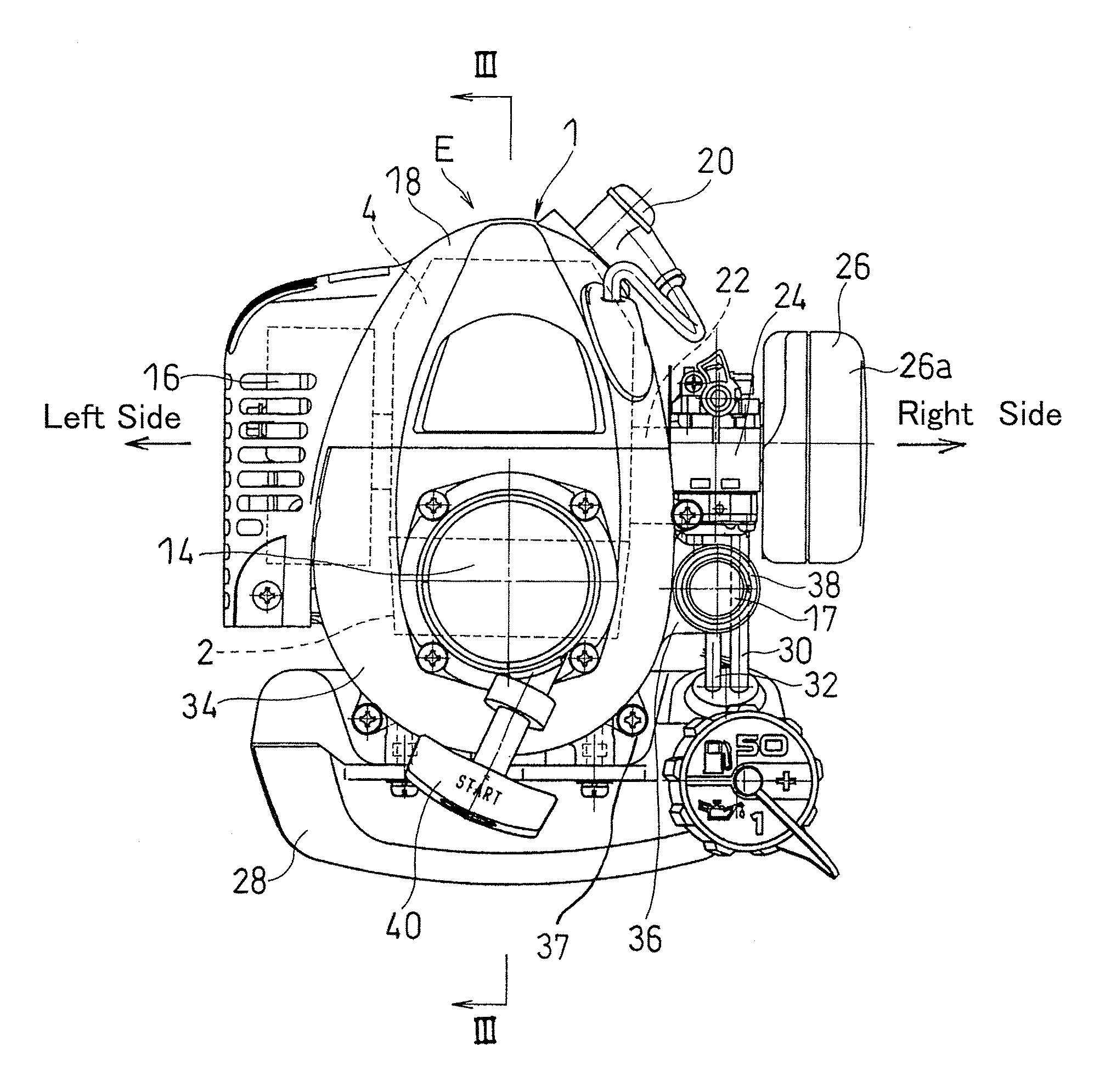
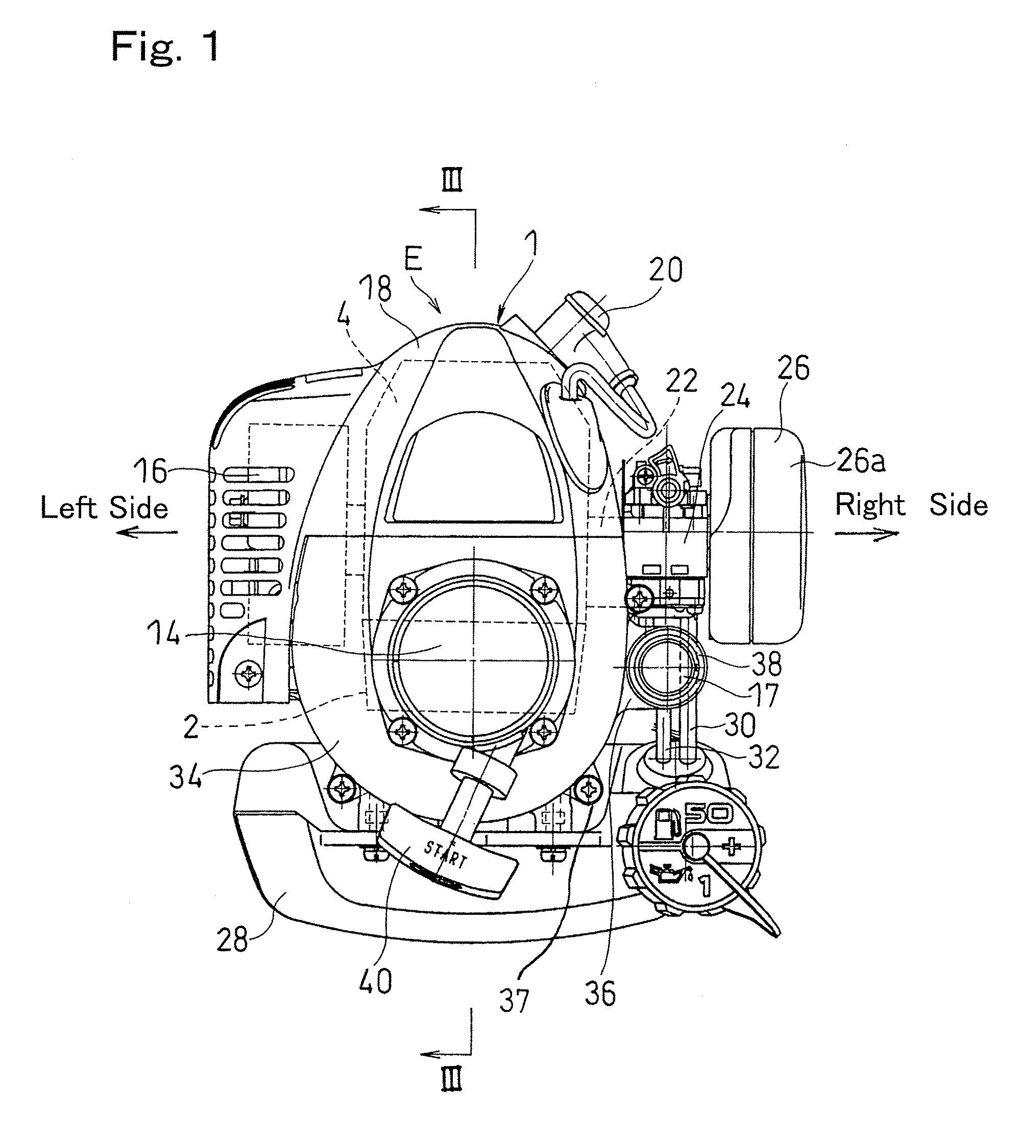
[0022]FIG. 1 illustrated a front elevational view of a combustion engine according to a preferred embodiment of the present invention, FIG. 2 illustrates a side view of the combustion engine, and FIG. 3 illustrates a cross-sectional view taken along the line III-III in FIG. 1. Referring particularly to FIG. 3, the combustion engine E includes an engine body 1 made up of crankcase 2 and a cylinder block 4 mounted atop the crankcase 2. The cylinder block 4 includes a cylinder 4a having a cylinder bore and a cylinder head 4b formed integrally with the cylinder 4a. A piston 5 is reciprocatingly accommodated within the cylinder bore for movement up and down.

[0023]The crankcase 2 rotatably supports a crankshaft 6 by means of axially spaced apart bearings 7 and 9 with the crankshaft 6 extending in a direction longitudinally of the engine body 1. The crank...


PUM

PropertyMeasurementUnit
Areaaaaaaaaaaa

Abstract

A combustion engine includes a carburetor, which is a fuel supply device for introducing fuel into an intake air of the engine, and a fan housing for enclosing a cooling fan mounted on a front end portion of a crankshaft. The fan housing is formed with a flange so as to extend towards a position proximate to the carburetor, and a manually operable priming pump is fitted to the flange.

Description

BACKGROUND OF THE INVENTION[0001]1. Field of the Invention[0002]The present invention relates to a compact size combustion engine for use in a brush cutter or a hedge trimmer.[0003]2. Description of the Prior Art[0004]In this kind of combustion engine, a priming pump 42 is generally secured to a lower portion of a carburetor 41 that protrudes laterally outwardly of an engine body 1 as shown in FIG. 4. The carburetor 41 used therein is of, for example, a diaphragm type that is operable in such a manner that when the priming pump 42 is driven, a quantity of fuel can be drawn into a metering chamber (not shown) defined in the carburetor 41. In such case, the priming pump 42 is positioned in a deep inner region beneath the carburetor 41 as clearly shown in FIG. 5, and accordingly, the presence of fuel tubes 43 and 44 nearby interfere often the manipulability of the carburetor 41.[0005]Also, the Japanese Laid-open Patent Publication No. H10-311227, published Nov. 24, 1998, discloses the ...

Claims


Application Information

Patent Timeline
IPC IPC(8): F02M1/16
CPCF02M1/16
Inventor YUASA, TSUNEYOSHI
Owner KAWASAKI HEAVY IND LTD
Why Eureka
Try Eureka