
Foam Shipping Package and Method

a packaging and foam technology, applied in the field of shipping packages, can solve the problems of increasing shipping costs, requiring large mechanical devices, and heavy containers or cases

Inactive Publication Date: 2008-04-24
MEYER KARL ROBERT
View PDF11 Cites 13 Cited by
  • Summary
  • Abstract
  • Description
  • Claims
  • Application Information

AI Technical Summary

Problems solved by technology

In the foregoing approach, one is often faced with transporting a shipping container or crate having greater weight or a larger size than needed, thus increasing the shipping costs.
Frequently, these containers or cases are very heavy and require large mechanical devices to facilitate their movement.
Furthermore, they often do not provide adequate interior protection of the article being shipped.
Movement within the interior of the container, such as from shifting or jolting of packaged loads, may damage the packaged articles, which leads to costly damage claims or return of such articles.
Prior containers or crates also often do not provide adequate protection from the weather and all of its elements.
The proper handling of moisture or condensation is a common challenge when properly packing the interior of these shipping containers.
Containers or crates are often not either reusable or returnable due to the weight or precise nature of their construction, which further may increase shipping costs.
In addition, containers or crates often cannot be inspected during the transportation of the article without unpacking the entire shipment and all its contents.
This often requires special tools and significant time of labor that may lead to an inspector having to re-pack the article.
However, the inspector typically lacks the appropriate packing expertise to do this re-packing in an optimal way.
This lack of expertise typically slows the transport of the articles and may jeopardize the safe shipment of the articles due to the improper re-packing by the inspector.

Method used


Image

  • Foam Shipping Package and Method
  • Foam Shipping Package and Method
  • Foam Shipping Package and Method

Examples


case 100

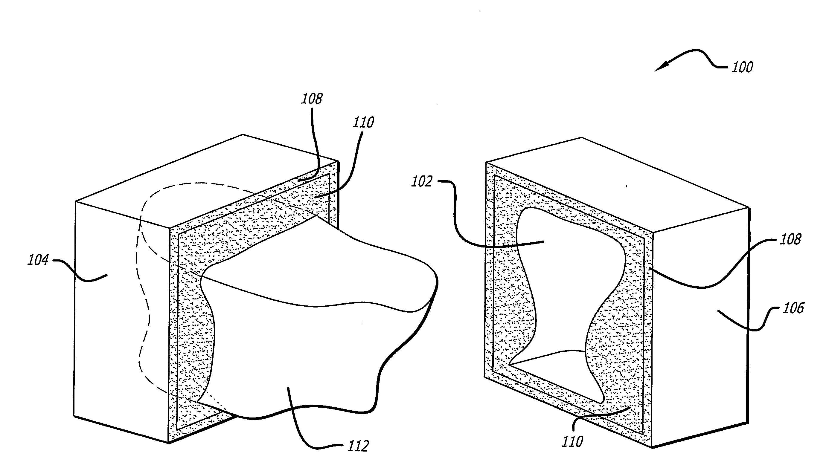
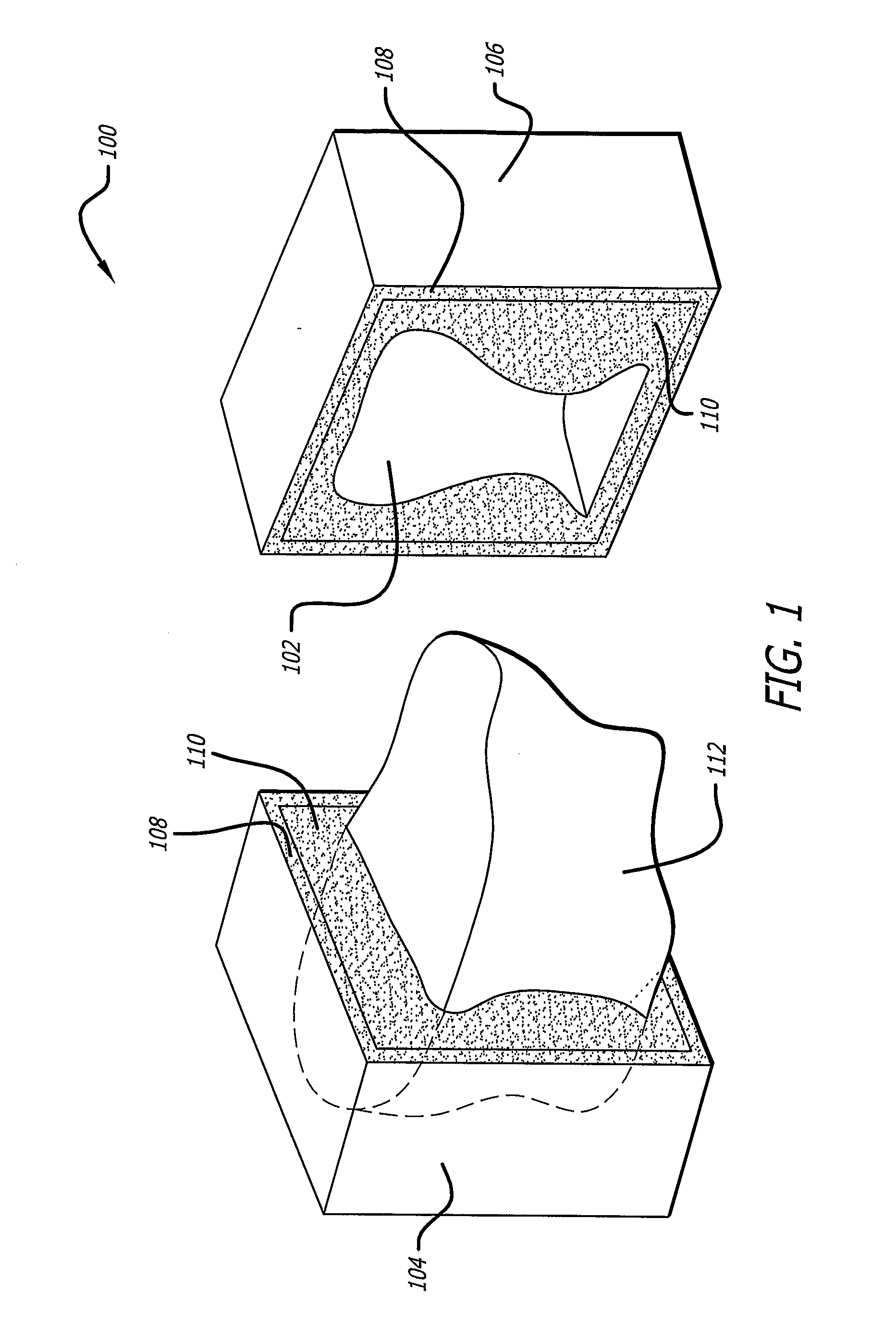
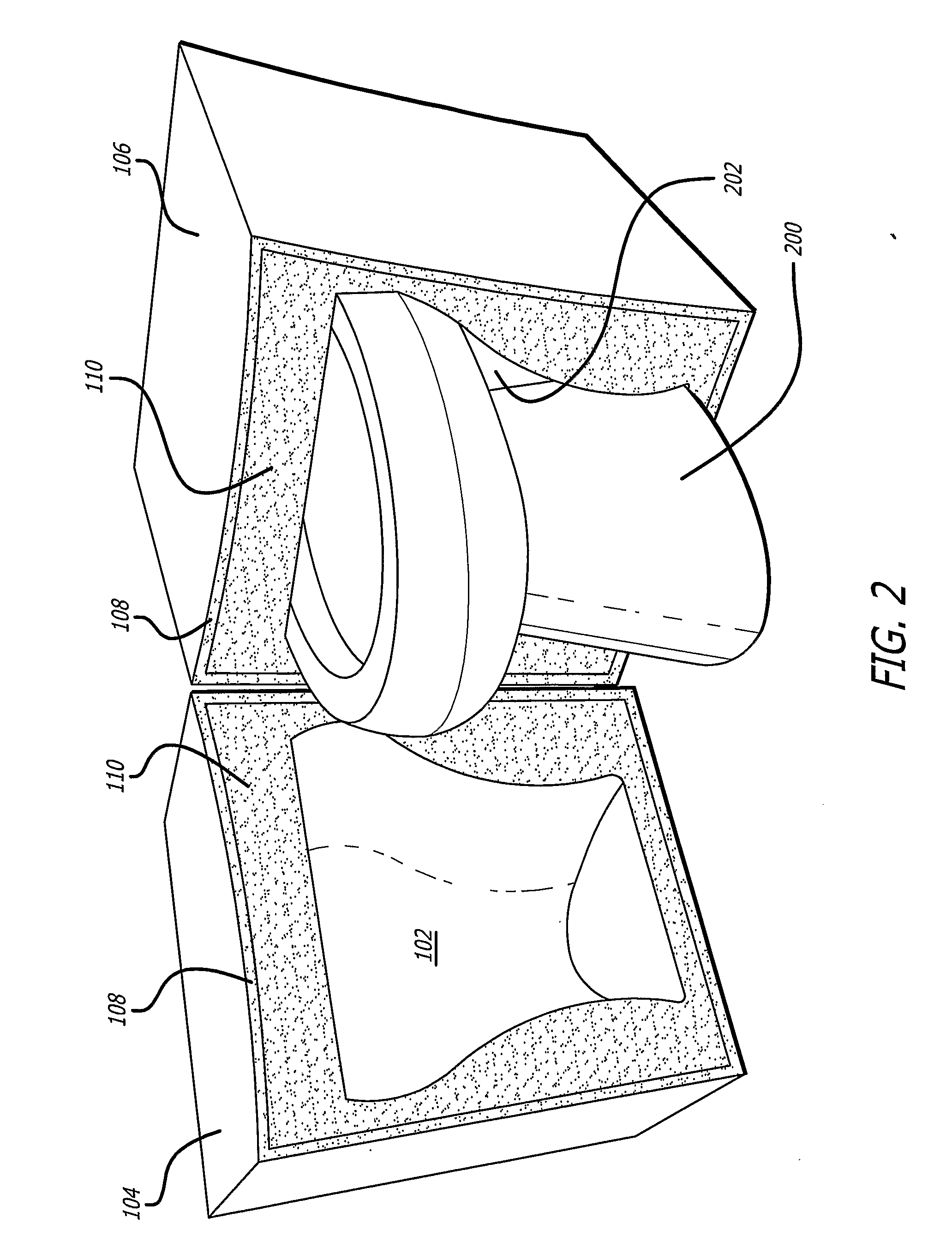
[0054]Packaging case 100 may include interior cavities (not shown) for holding other articles in addition to article 200. These articles may be, for example, a group of related articles used in manufacturing a particular module or sub-assembly upon arrival at a shipping destination.

[0055]Inner foam layer 110 may have an average density greater than, for example, about 0.05 lb / ft3, with a typical range, for example, between about 0.05 to 6 lb / ft3. Outer foam layer 108 may have an average density greater than, for example, about 10 lb / ft3, with a typical range, for example, between about 10 to 70 lb / ft3. The average density of outer foam layer 108 may typically be, for example, more than 1,000% greater than the average density of inner foam layer 110. Multiple combinations of densities for each of the foam layers may be used for different levels of protection.

[0056]In some instances, by way of example, a one-side packaging case or drop-in case designed for use in shipping a transmissi...


PUM

PropertyMeasurementUnit
Fractionaaaaaaaaaa
Fractionaaaaaaaaaa
Densityaaaaaaaaaa

Abstract

A reusable packaging case for an article comprises an inner foam layer having an interior cavity for holding the article. The inner foam layer surrounds at least a portion of the interior cavity. An outer foam layer substantially surrounds the inner foam layer The outer foam layer may have a density greater than the density of the inner foam layer. The inner foam layer may be formed using a plug having the same shape as the article to be later packaged in the case for shipping. The packaging case may optionally contain numerous additional inner foam layers of varying densities and thicknesses. Many substantially identical packaging cases, such as for shipping numerous identical articles coming off of an assembly line, may be formed using the plug.

Description

RELATED APPLICATIONS[0001]This application is a non-provisional application claiming benefit under 35 U.S.C. sec. 119(e) of U.S. Provisional Application Ser. No. 60 / 587,389, filed Jul. 13, 2004 by Karl Robert Meyer (titled BIKINI COVERS, INC. HIGH-DENSITY FOAM SHIPPING CASE (HDFC) DETAIL), which is incorporated by reference herein.BACKGROUND[0002]1. Field[0003]The present disclosure generally relates to shipping packages, and more particularly to a shipping package using protective foam.[0004]2. General Background[0005]The shipping and packaging industry uses a variety of containers and materials for shipping articles. Foam structures are one form of protective packaging used for shipping. For example, foam pieces may be used on the ends of an article to suspend it within a cardboard box or a wooden shipping crate.[0006]The container designs and materials used to form containers and otherwise package articles are selected based on various factors typically including the desire to mi...

Claims


Application Information

Patent Timeline
IPC IPC(8): B65D81/03B29C41/00B65D81/113
CPCB65D81/022B65D2203/10B65D85/30B65D81/20Y02W30/80
Inventor MEYER, KARL ROBERT
Owner MEYER KARL ROBERT
Learn More