
Multifunctional Reactive Composite Structures Fabricated From Reactive Composite Materials

Inactive Publication Date: 2008-04-24
REACTIVE NANOTECH
View PDF13 Cites 14 Cited by
  • Summary
  • Abstract
  • Description
  • Claims
  • Application Information

AI Technical Summary

Benefits of technology

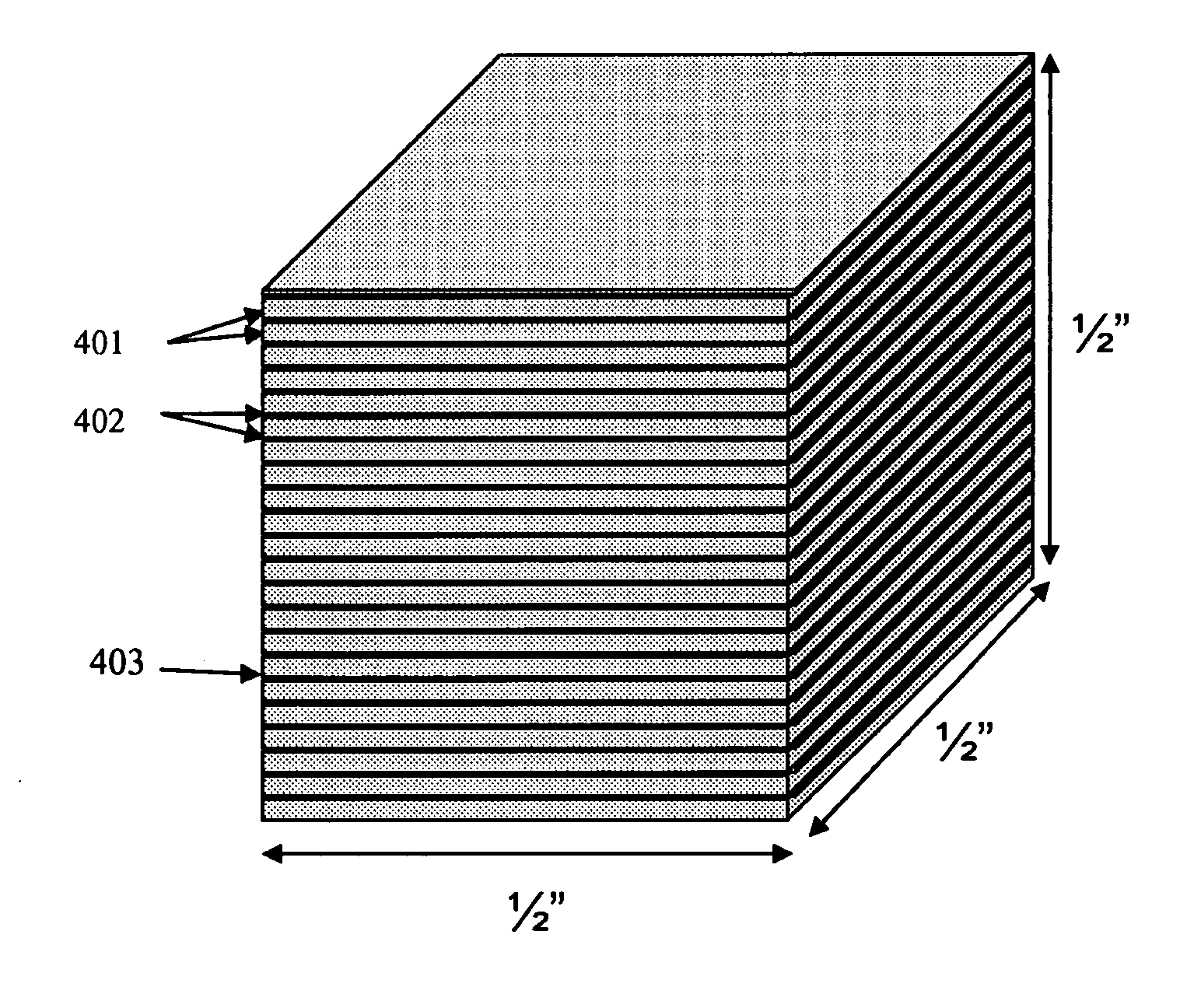
[0024]Utilizing RCMs as energetic components is simplified by joining two or more pieces of RCM together into a single structure. Current fabrication methods restrict individual pieces of RCM to small sizes and thin gauges, but these limitations can be overcome by methods of the present invention for joining several RCM pieces together along the edges, by laminating thin sheets together to form a thicker bulk material, or by some combination of these two methods. Pieces of RCM may be joined together by one of a variety of joining technologies (such as epoxy, solder, brazing, and welding) to form a thick, large area material with improved strength and stiffness and / or increased energy output.

Problems solved by technology

Current structural materials typically possess limited energy release properties.
Common structural materials such as steels, aluminum, or composites provide only mechanical strength and stiffness, and do not provide any significant energy release if stimulated with a pulse of thermal or kinetic energy.
In fact, these materials may absorb energy and degrade the energetic properties of devices such as munitions and shaped charges.
On the other hand, the low cost and ease of formability of these materials, as well as their good mechanical properties, make them difficult to replace.
Conversely, current energetic materials typically have limitations regarding their mechanical properties or their ability to be formed into strong and stiff structural elements.
Hydrocarbon-based and nitrogen-based energetic materials, such as many explosives, display low strength and stiffness compared to structural materials such as metals.
The formability of many explosives is also limited to casting and extrusion since the sensitivity of the majority of explosives prohibits machining or other standard means of shaping.
7.87 g / cc for steel), a fact that may hinder or prohibit their use as structural members in certain applications such as penetrators, where high mass density is preferred.
Currently, the dangers inherent in energetic materials limit their manufacture and restrict their utilization in applications as structural members or components.
However, both powder compacts and powders dispersed in a binder typically display poor mechanical properties.
Many powder compacts are brittle or friable and difficult to machine due to their nature as particle agglomerations and their inherent porosity.
Also of concern are the health and safety hazards associated with toxic or flammable powders.
Vapor-deposited RCMs, described in detail in U.S. Pat. No. 6,736,942 to Weihs, et al., possess high strength and stiffness, but generally have low ductility or formability, limiting the shapes and forms into which they can be manufactured.
Vapor-deposited RCMs are also technically challenging and expensive to fabricate in large or thick sections, and have to date been available only as thin foils.
Available material geometries and properties impose limitations on the applications of vapor-deposited material on a larger scale, e.g. in macroscopic structural applications requiring large volumes of material, energetic applications requiring high heat per unit volume, or applications requiring the energetic component to have a complex geometry.

Method used


Image

  • Multifunctional Reactive Composite Structures Fabricated From Reactive Composite Materials
  • Multifunctional Reactive Composite Structures Fabricated From Reactive Composite Materials
  • Multifunctional Reactive Composite Structures Fabricated From Reactive Composite Materials

Examples


Embodiment Construction

[0049]The following detailed description illustrates the invention by way of example and not by way of limitation. The description enables one skilled in the art to make and use the invention, and describes several embodiments, adaptations, variations, alternatives, and uses of the invention, including what is presently believed to be the best mode of carrying out the invention.

[0050]The present invention sets forth different methods for making reactive composite structures (RCS) having components or bodies which consist of reactive composite materials (RCM), via various assembly, joining, and shaping methods. The reactive composite materials in the reactive composite structure can then be ignited at a subsequent point in time to carry out an intended function of the reactive composite structure. The invention additionally sets forth characteristics of the RCM required to make these methods feasible.

[0051]Fundamental to the fabrication methods discussed below is the tunability of RC...


PUM

PropertyMeasurementUnit
Mechanical strengthaaaaaaaaaa
Fracture toughnessaaaaaaaaaa
Chemically inertaaaaaaaaaa

Abstract

A reactive composite structure having selected energetic and mechanical properties, and methods of making reactive composite structures enabling the construction of complex parts and components by machining and forming of reactive composite materials without compromising the energetic or mechanical properties of the resulting reactive composite structure.

Description

CROSS-REFERENCE TO RELATED APPLICATIONS[0001]The present application is related to, and claims priority from, U.S. Provisional Application No. 60 / 692,857 filed on Jun. 22, 2005, which is herein incorporated by reference.[0002]The present application is further related to, and claims priority from, U.S. Provisional Application No. 60 / 692,822 filed on Jun. 22, 2005, which is herein incorporated by reference.[0003]The present application further is related to, and claims priority from, U.S. Provisional Application No. 60 / 740,115 filed on Nov. 28, 2005, which is herein incorporated by reference.STATEMENT REGARDING FEDERALLY SPONSORED RESEARCH[0004]The United States Government has certain rights in this invention pursuant to Award 70NANB3H3045 supported by NIST through its Advanced Technology Program.BACKGROUND OF THE INVENTION[0005]This invention relates to energetic materials. In particular, it concerns methods for fabricating useful assemblies and components from reactive composite ma...

Claims


Application Information

Patent Timeline
IPC IPC(8): B23K31/00
CPCC06C15/00F42B12/42F42B4/26F41J2/02
Inventor WEIHS, TIMOTHY P.LUNKING, DAVID M.HEIAN, ELLEN M.XUN, YUWEIBOWMAN, RICHARDCATIG, GARYHEERDEN, DAVID VANVALLIAPPAN, SOMASUNDARAMKNIO, OMARGRZYB, JOSEPH
Owner REACTIVE NANOTECH
Learn More