Light-Emitting Diode Illumination Source

a technology of light-emitting diodes and illumination sources, which is applied in the field of illumination sources, can solve the problems of not having flat spectral distributions of conventional led light sources, not including sufficient components for all wavelengths, and difficult for such a light source to show colors with wavelengths corresponding to valleys when used for illumination, and difficult for the light source to show red particularly

Inactive Publication Date: 2008-04-24
SHOWA DENKO KK
View PDF2 Cites 2 Cited by
  • Summary
  • Abstract
  • Description
  • Claims
  • Application Information

AI Technical Summary

Benefits of technology

[0011] The light emitting diode illumination source of the present invention has a flat spectral distribution containing light components with all wavelengths in green to red regions, and thereby can achieve illumination close to natural light, ext...

Problems solved by technology

However, conventional LED light sources do not have flat spectral distributions and do not include sufficient components for all wavelengths.
For example, since a typical example of a spectral distribution curve of a three-in-one type light source as shown in FIG. 4 has sharp peaks within the blue, green, and red wavelength regions and deep valleys between the peaks, it is difficult for such a light source to show colors with wavelengths cor...

Method used


Image

  • Light-Emitting Diode Illumination Source
  • Light-Emitting Diode Illumination Source
  • Light-Emitting Diode Illumination Source

Examples


example 1

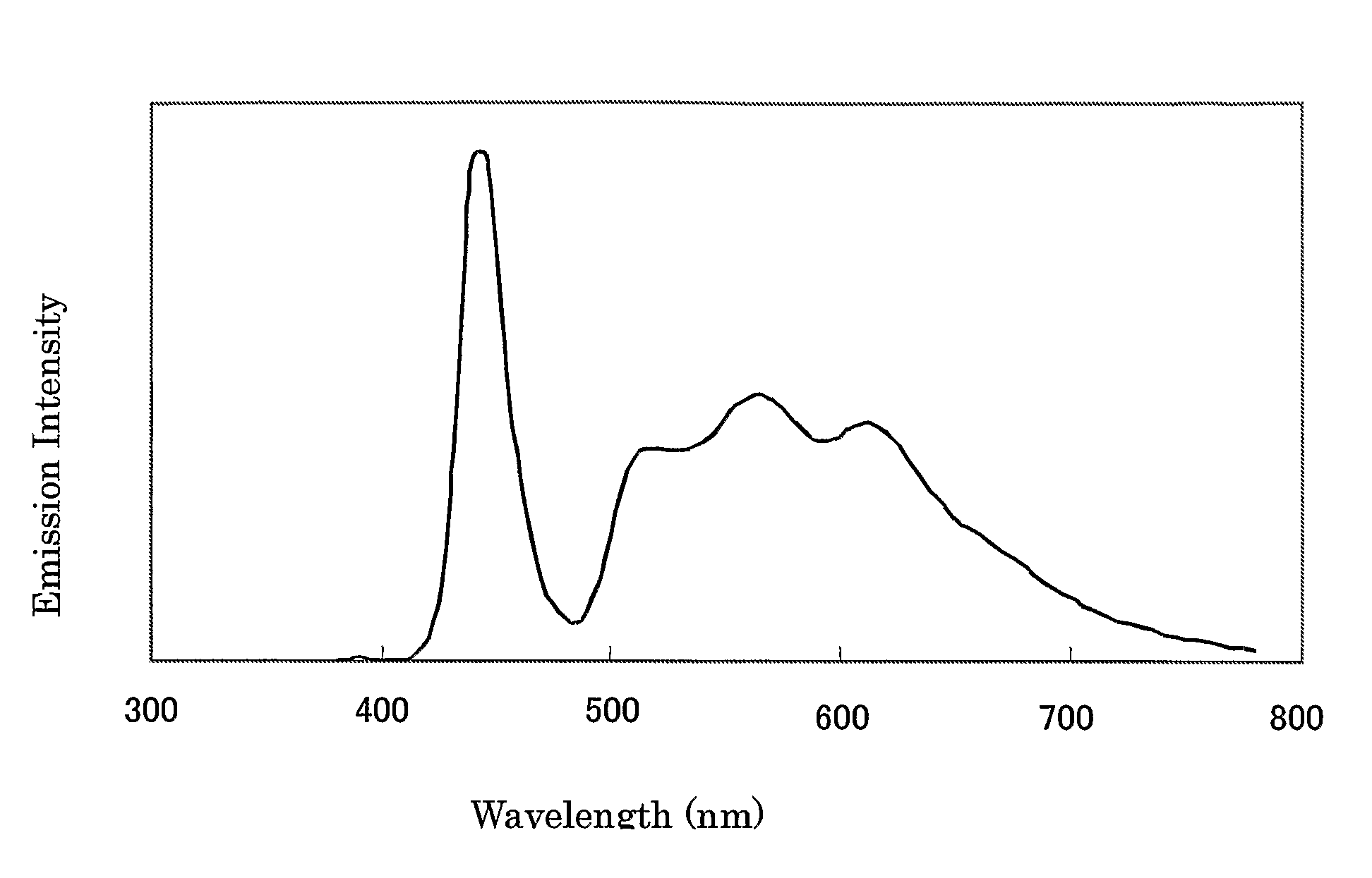
[0040] An InGaN light emitting diode chip having a dominant emission wavelength of 455 nm and an emission output of 4.6 mW was mounted in a surface mount package of 3 mm×2.5 mm×2.5 mm in outer size. Then, 4.9 mg of the iridium complex (E2), 0.4 mg of (E17), and 1.7 mg of (E16) were dispersed in 10 g of an epoxy resin (refractive index 1.6, EL438 available from Sanyu Rec Co. Ltd.), poured into a concavity of the surface mount package, and heat-treated at 120° C. for 4 hours to cure the resin, whereby a photoluminescent layer was formed.

[0041] The obtained LED light source was energized at 3.27 V and 20 mA and lighted. The emission spectrum thereof is shown in FIG. 1. There were three peaks in the wavelength region of 480 to 700 nm, and the maximum intensity was at 575 nm. There were two valleys between the peaks, and the minimum intensity was at 530 nm. The ratio of the intensities was 100:78. The emission intensity at 650 nm was 55% of the maximum intensity in the wavelength region...

example 2

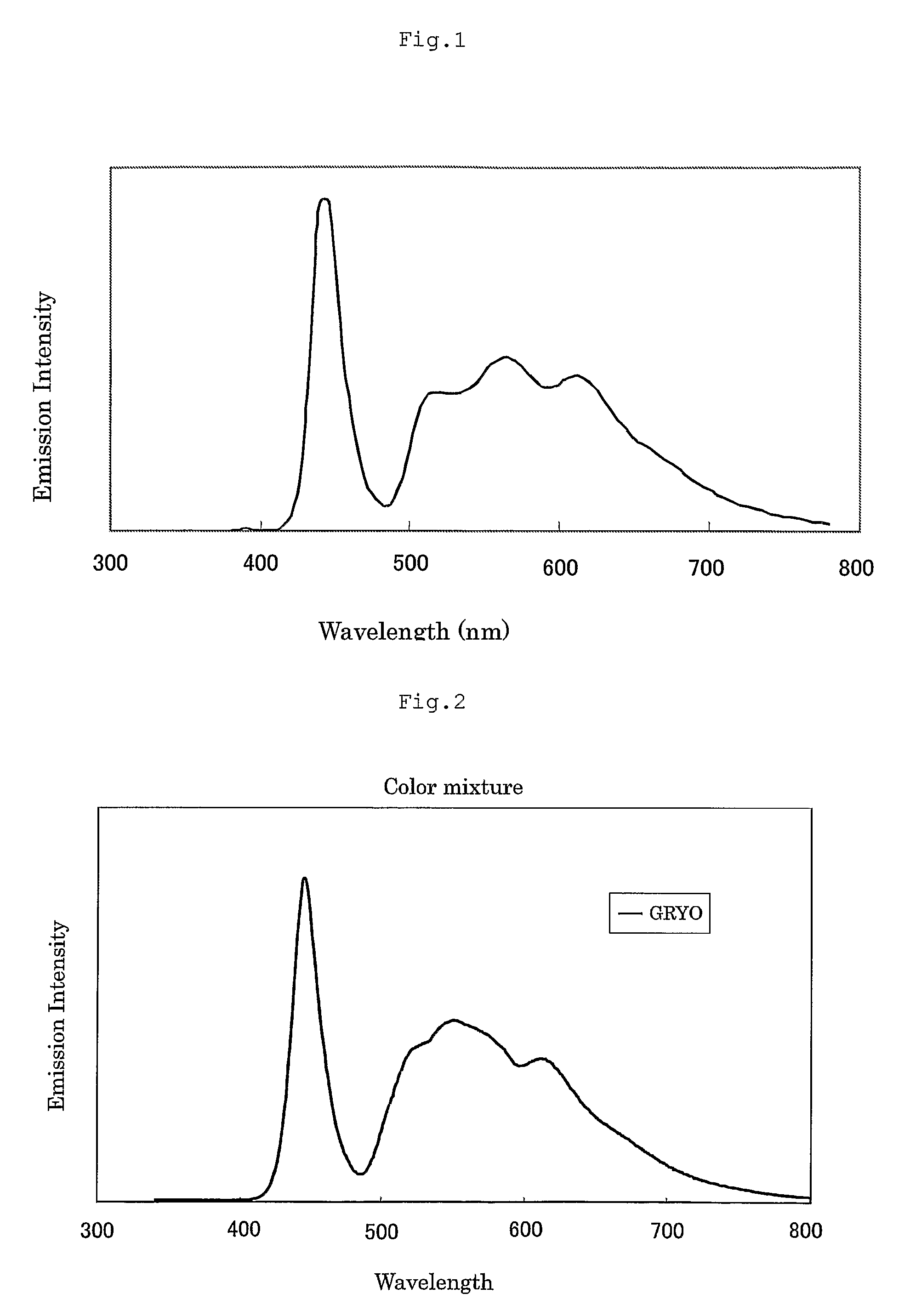
[0044] An InGaN light emitting diode chip having a dominant emission wavelength of 455 nm and an emission output of 4.6 mW was mounted in a surface mount package of 3 mm×2.5 mm×2.5 mm in outer size. Then, 4.9 mg of the iridium complex (E2), 0.5 mg of (E17), 0.6 mg of (E14), and 1.0 mg of (E16) were dispersed in 10 g of an epoxy resin (refractive index 1.6, EL438 available from Sanyu Rec Co. Ltd.), charged into a concavity of the surface mount package, and heat-treated at 120° C. for 4 hours to cure the resin, whereby a photoluminescent layer was formed.

[0045] The obtained LED light source was energized at 3.27 V and 20 mA and lighted. The emission spectrum thereof is shown in FIG. 2. There were four peaks in the wavelength region of 480 to 700 nm, and the maximum intensity was at 553 nm. There were three valleys between the peaks, and the minimum intensity was at 597 nm. The ratio of the intensities was 100:75. The emission intensity at 650 nm was 51% of the maximum intensity in th...


PUM


Abstract

The invention provides light emitting diode illumination source having excellent properties as an illumination source such as a flat spectral distribution in the wavelength region from green to red and a sufficient emission intensity in the red region, comprising a light emitting diode having multiple peaks with a half-value width of 20 nm or more within a range from 480 to 700 nm in a spectral distribution, wherein the minimum of the intensities of the valleys between the peaks in the wavelength range from 480 to 700 nm is 65% or more of the maximum peak intensity in the same range, and an illuminator and a backlight for a liquid crystal display using the illumination source.

Description

CROSS-REFERENCE TO RELATED APPLICATIONS [0001] This is an application filed pursuant to 35 U.S.C. Section 111(a) with claiming the benefit of U.S. provisional application Ser. No. 60 / 632,986 filed Dec. 6, 2004 and U.S. provisional application Ser. No. 60 / 653,996 filed Feb. 18, 2005 under the provision of 35 U.S.C. 111(b), pursuant to 35 U.S.C. Section 119(e) (1).TECHNICAL FIELD [0002] The present invention relates to an illumination source using a light emitting diode (LED), an illuminator, and a backlight for a liquid crystal display. BACKGROUND ART [0003] Light emitting diode devices are improved remarkably in terms of light emitting efficiency and are free from mercury which is a toxic substance, whereby use thereof for illumination instead of conventional fluorescent lamps has energetically been studied in recent years. It is preferred that an illumination source emits a light having a spectral distribution close to that of sunlight. Thus, it is preferred that the illumination s...

Claims


Application Information

Patent Timeline
IPC IPC(8): H01L33/00H01L33/32H01L33/56
CPCC09K11/06C09K2211/1029C09K2211/185H05B33/14H01L51/006H01L51/5036H01L33/502H10K85/633H10K50/125
Inventor SHINOZAKI, KENJIHANAWA, KENZOKATO, TSUYOSHITAKAHASHI, YOSHIAKI
Owner SHOWA DENKO KK
Why Eureka
Try Eureka