Mechanical Seal Device

a mechanical seal and sealing device technology, applied in the direction of engine seals, mechanical apparatus, engine components, etc., can solve the problems of difficult part management and control, difficult to provide an effect of cooling to a source of sliding frictional heat, and increase the danger of contaminating oil or chemical fluid located in the outer circumferential side with quenching fluid, etc., to achieve the effect of easy replacement of parts in the disassembly of the mechanical seal devi

Active Publication Date: 2008-04-24
EAGLE INDS
View PDF10 Cites 20 Cited by
  • Summary
  • Abstract
  • Description
  • Claims
  • Application Information

AI Technical Summary

Benefits of technology

[0023] According to the mechanical seal device of the fourth embodiment relative to the present invention, the first seal ring fits the fit surface of the seal cover and the second seal ring fits the seal collar and the relatively sliding seal face is sealably secured from the outboard side to the sliding ...

Problems solved by technology

This configuration finds it difficult that it is hard to provide an effecting cooling to a source of sliding frictional heat, i.e., the relatively opposing sliding faces of the rotary seal ring 103 and the stationary seal ring 103, from the outer circumferential side of a wide surface area.
In particular, providing a cooling to the relatively opposing sliding sea...

Method used


Image

  • Mechanical Seal Device
  • Mechanical Seal Device
  • Mechanical Seal Device

Examples


first embodiment

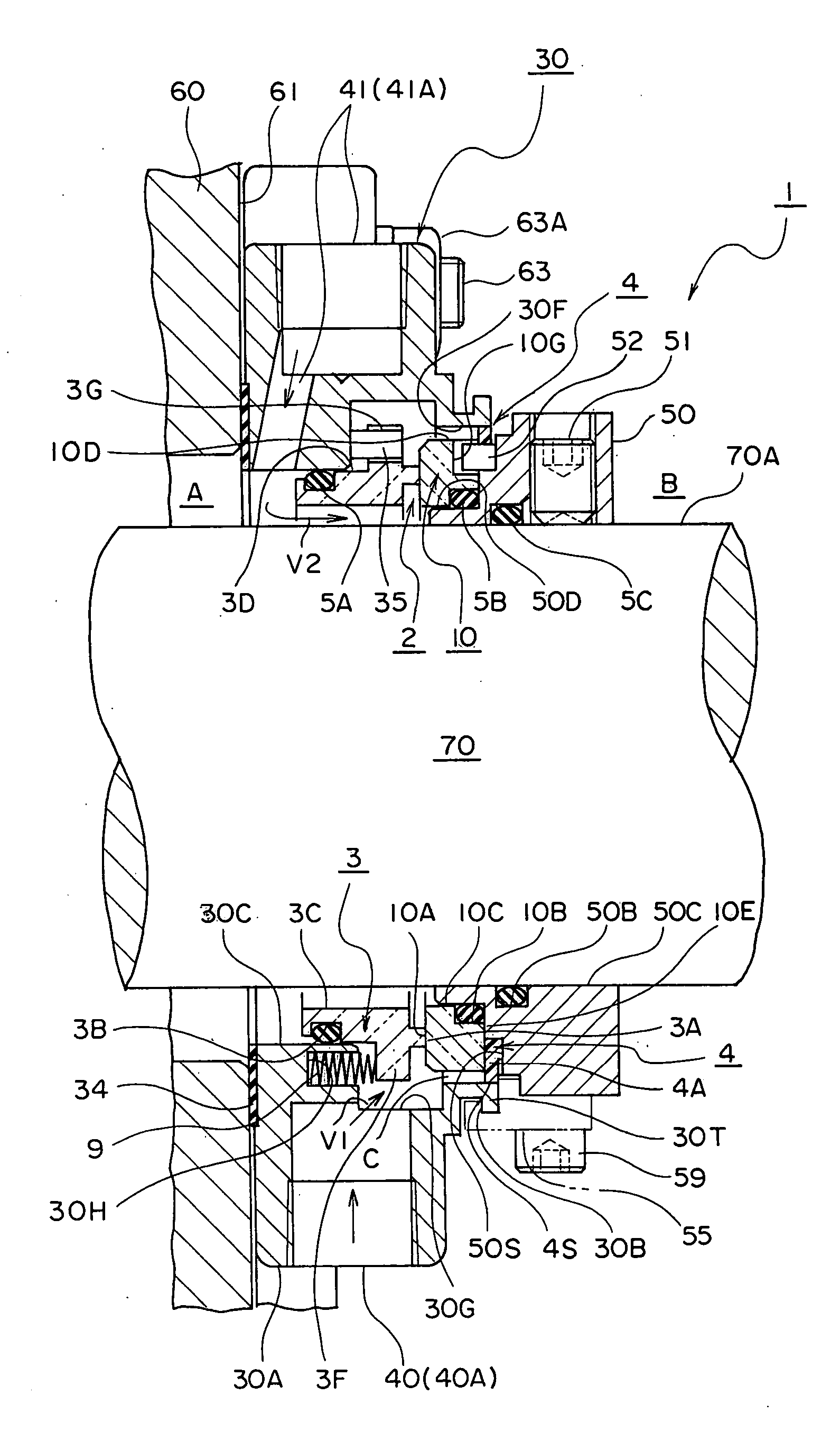
[0032]FIG. 1 shows a mechanical seal device 1 as a first embodiment relative to the present invention. There is disposed a rotary shaft 70 extending through a shaft bore hole of an apparatus main body (casing) 60. The mechanical seal device 1 is mounted onto an outboard wall face 61 via a seal cover 30 wherein the outboard wall face 61 is located around the circumference of the shaft bore entrance of the apparatus main body 60. In the apparatus main body 60, there are 4 pieces of stud bolts disposed at four different places along the circumference of the outboard wall face 61. The rotary shaft 70 is supported in freely rotatable a manner by means of a bearing, not shown, which is mounted to the shaft bore. A space within the bore hole of the apparatus main body 60 corresponds to an inboard space A while the opposite (outward) the apparatus main body 60 with respect to the mechanical seal device 1 corresponds to an outboard B.

[0033] Further details on the mechanical seal device 1 wil...

second embodiment

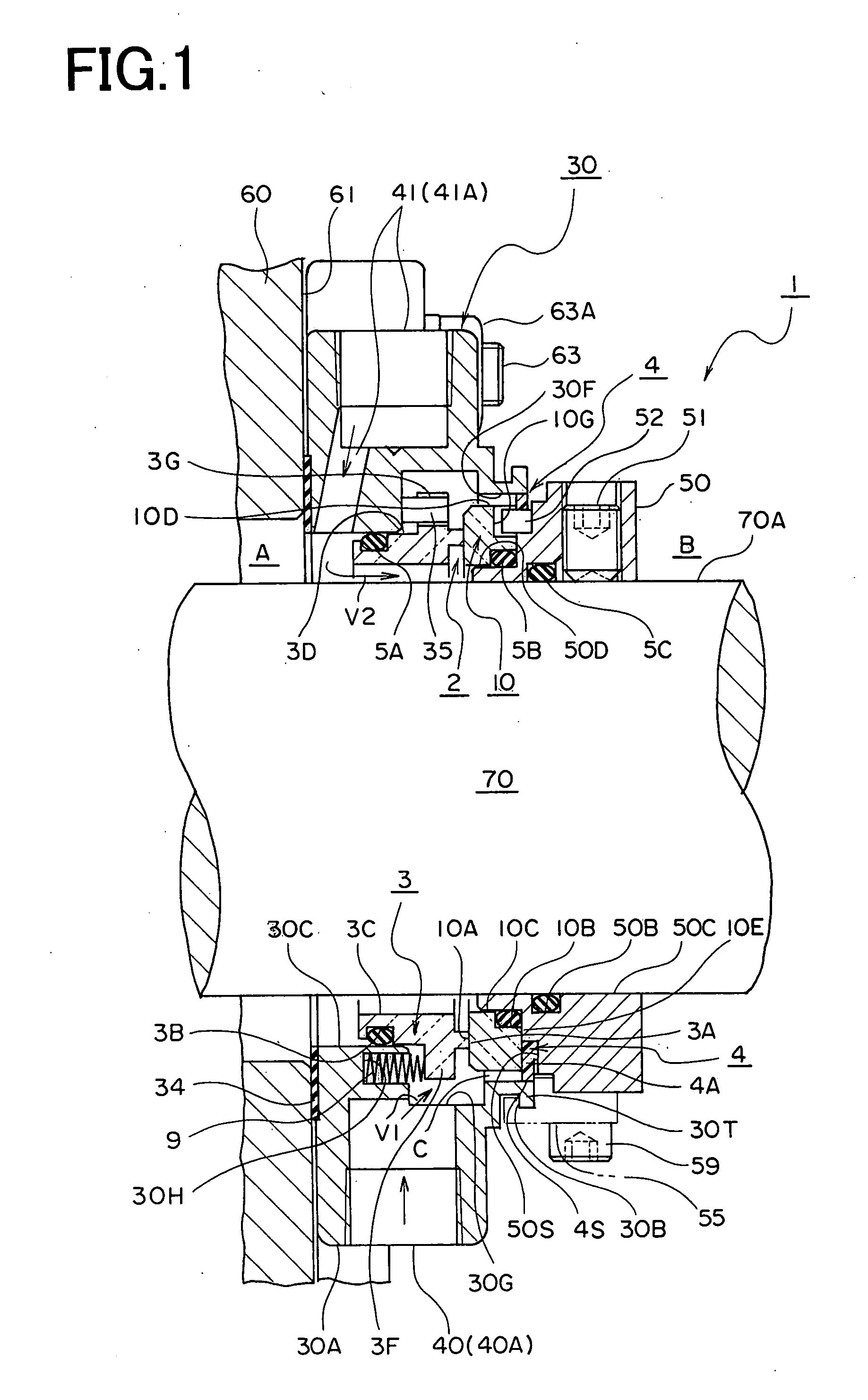
[0044]FIG. 3 shows a cross sectional view of a portion of packing 4 as a second embodiment related to the present invention. This packing 4 disposes discharge means 4T on ring-shaped side wall thereof in which radially extending projected portions and radially extending recessed portions are lined up alternately along the circumference. The discharge means 4T consists of projected portions 4T1 and recessed portions 4T2. Other names are the same as those of reference numerals used in FIG. 2, i.e., seal portion 4A, installation portion 4B, fit contact face 4C and seal contact face 4S. This discharge means 4T pushes the quenching liquid V1 (refer to FIG. 1) in the small clearance C back to inside the annular groove 30G and prevents contaminants attached on the seal contact face 4S from wearing the seal contact face 4S. The discharge means 4T, at the same time, pushes away the contaminants contained in the quenching liquid V1 toward annular groove 30G side, thereby improving seal abilit...

third embodiment

[0045]FIG. 4 is a cross sectional view of a portion of packing 4 as a third embodiment related to the present invention. This packing 4 has approximately the same form as that shown by the same reference numerals in FIG. 2. A difference resides in that there is disposed a discharge means 4S1 of a spiral groove design on the quenching liquid V1 (refer to FIG. 1) side of the seal contact face 4S, thereby pushing back the quenching liquid V1 enhancing seal ability of the packing 4. This packing 4 is made of Fluoride Resin.

[0046] In the mechanical seal device 1 thus constructed, the quenching liquid V1 can provide an effective cooling against sliding frictional heat generated in the mechanical seal 2 and can prevent an occurrence of thermal damage or squeaking noise at the relative seal faces 3A, 10A. The cooling effect due to the quenching liquid V1 within the annular groove 30G enhances a seal performance of the respective relative seal faces 3A, 10A. Unlike the prior art, as no sleev...


PUM


Abstract

A mechanical seal in which cooling and cleaning of each seal ring and, in addition, lubrication of a slide seal surface are improved, which can be reduced in size, and whose assembly and disassembly are facilitated. The mechanical seal device has a seal cover (30) attached to an outer surface (61) of a device body, having a fitting surface (30C) through which a shaft is insertable, and forming a space section (30G) that is more on the outside (B) of a machine than the fitting surface (30C); a quenching path (40) penetrating through the space section (30G) and supplying quenching fluid into the space section (30G); an annular restriction section (30F) constructed in the seal cover (30) and provided more on the outside of the machine than the space section (30G); a first seal ring (3) having a movement surface (3D) that is sealingly movably fitted to the fitting surface (30C) of the seal cover (30) and having a seal surface (3A) inward of the space section (30G); a second seal ring (10) having a relative slide seal surface (10A) that can be in tight contact with the seal surface (3A) of the first seal ring (3) and having on its outer peripheral surface a seal surface (10D) that faces the restriction surface (30F); a seal collar (50) for holding the second seal ring (10) in a sealed state and sealingly fixed to the shaft; and a packing (4) in tight contact with the seal surface (10D) of the second seal ring (10) and with the restriction surface (30F) of the seal cover (30) to prevent the quenching fluid from leaking out of the machine.

Description

TECHNICAL FIELD [0001] The present invention relates generally to a mechanical seal device which enjoys a simple construction and is able to provide a cooling for the sliding seal faces of a mechanical seal. More particularly, the invention relates to a mechanical seal device of a cartridge type which is suitable for effecting a seal against highly viscous sealed fluid, slurry contained sealed fluid, sealed fluid made of chemical liquid or the like and prevents solid matters contained in the sealed fluid from being stuck on the sliding faces of the seal ring or from being trapped between the seal members to cause a generation of sliding frictional heat. BACKGROUND ART [0002] A mechanical seal device needs to have a simple construction and be straightforward for assembly / disassembly / inspection because it is applied to a mass-produced or massively processed apparatus such as automobiles or chemical devices. Additionally, a mechanical seal device needs to possess a construction achievi...

Claims


Application Information

Patent Timeline
IPC IPC(8): F16J15/34F16J15/38
CPCF16J15/348F16J15/3404F16J15/34
Inventor TAKAHASHI, HIDEKAZU
Owner EAGLE INDS
Why Eureka
Try Eureka