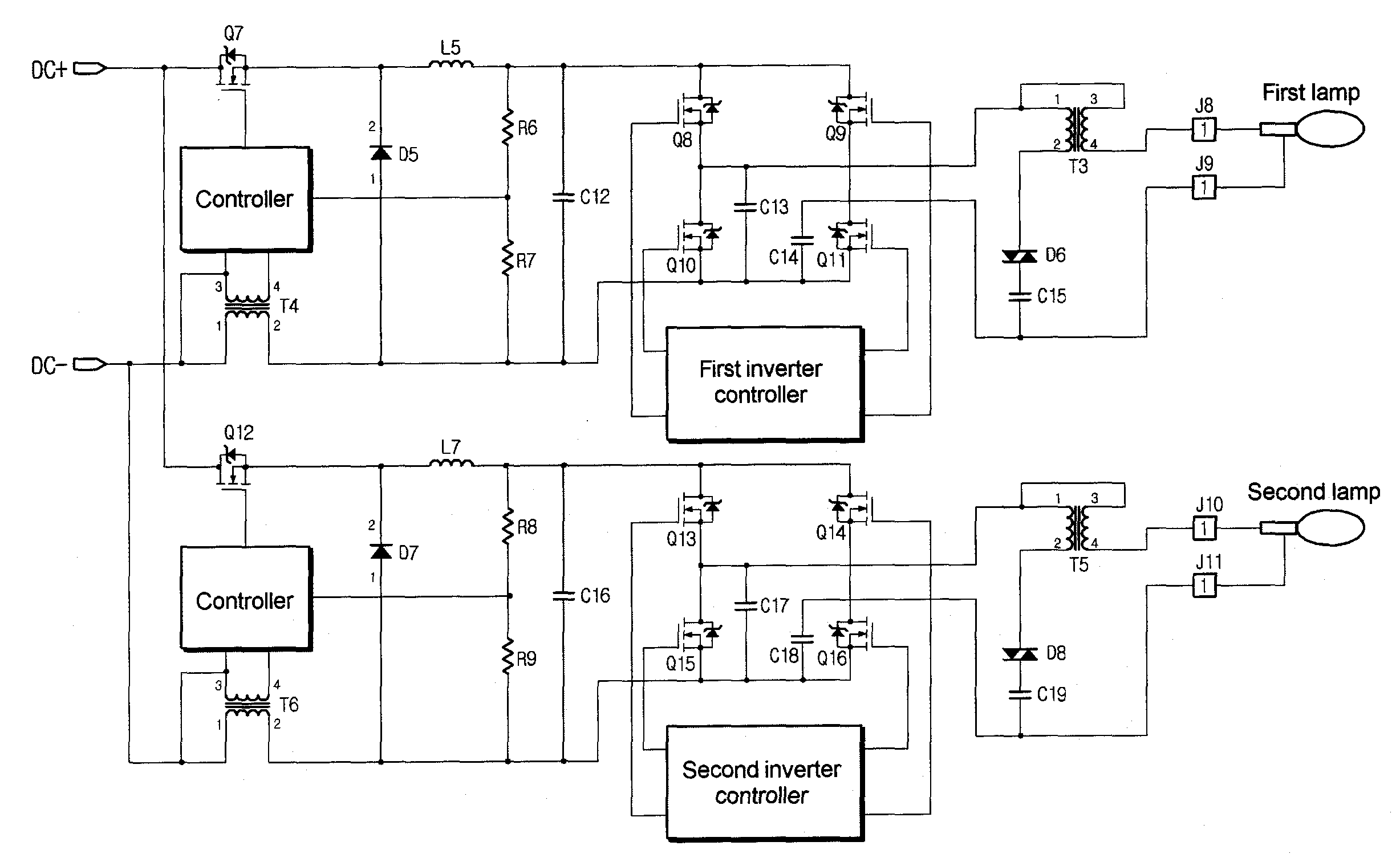
Ballast For High Intensity Discharge Lamps

a technology of electronic ballast and high intensity, which is applied in the direction of sustainable buildings, energy-saving lighting, machines/engines, etc., can solve the problems of not being able to simultaneously ignite two lamps with a single electronic ballast, and unable to develop a general electronic ballast suitable for hiding lamps, etc., to achieve the effect of improving the efficiency of electronic ballast, reducing the number of electronic ballast components, and reducing the production cost, size and weight of electronic ballas

Inactive Publication Date: 2008-04-24
SONG YOUNG JIN
View PDF5 Cites 4 Cited by
  • Summary
  • Abstract
  • Description
  • Claims
  • Application Information

AI Technical Summary

Benefits of technology

[0047] In addition, a power controller of the electronic ballast according to the present invention may be constructed in a current controlled type, so that it is possible to selectively igniting one lamp or two lamps without any circuit modification thereof.
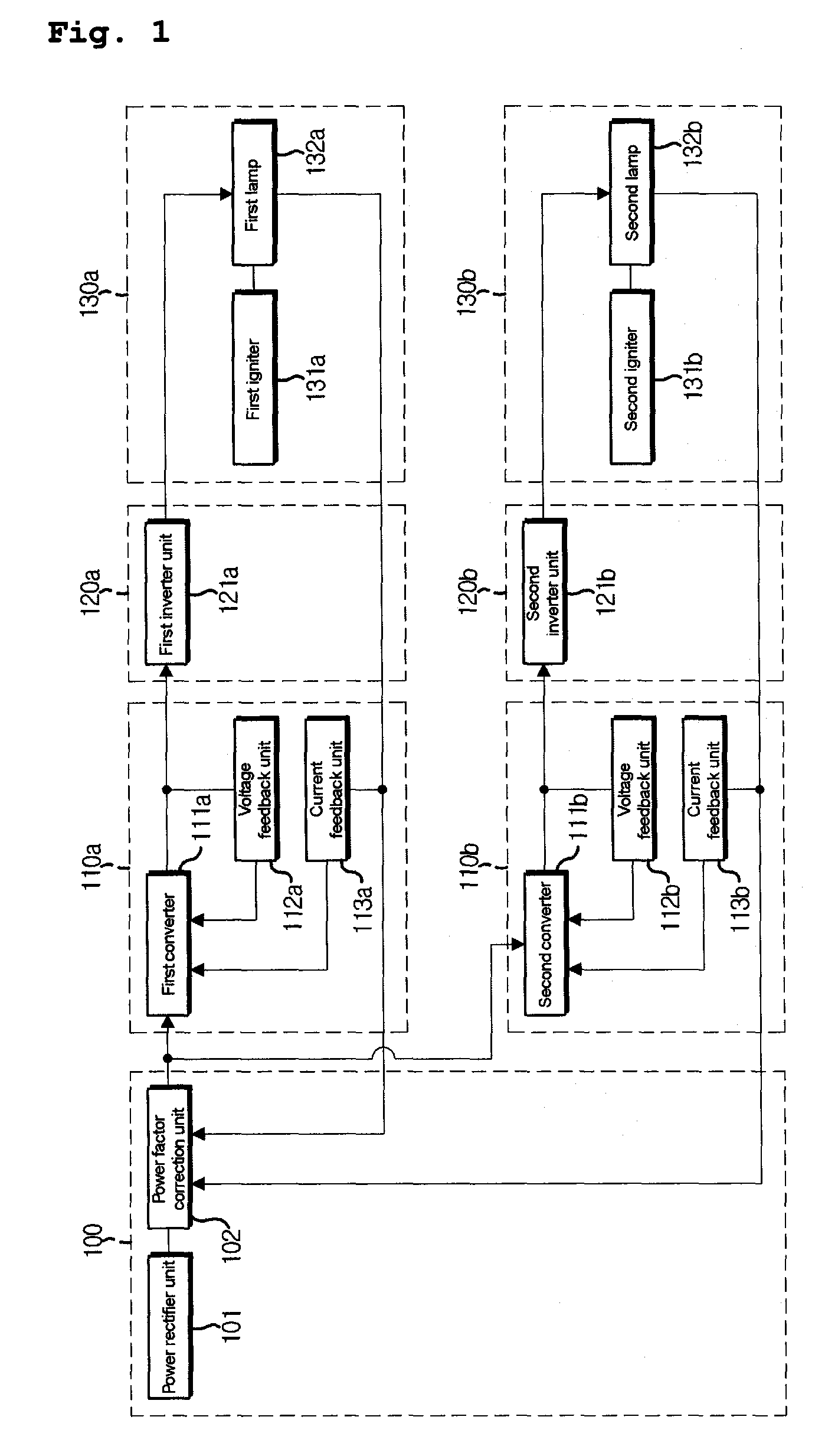
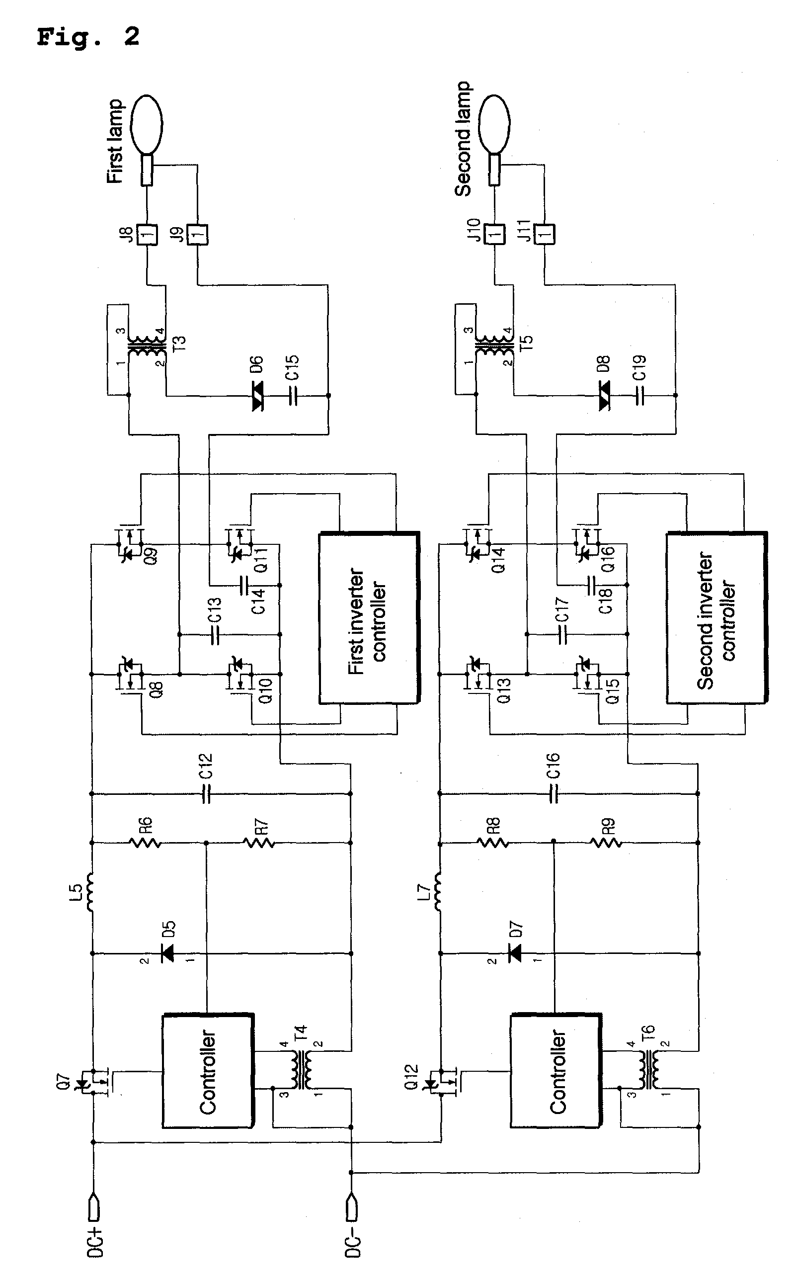
[0048] As described above, in a conventional multi-lamp electronic ballast, since the first power control unit, the second power control unit, the first inverter unit, the second inverter unit, the first igniter unit, and the second igniter unit are constructed in parallel, a large number of components are needed. However, according to the present invention, it is possible to reduce the number of components of the electronic ballast by half or less. Therefore, it is possible to reduce production cost, size, and weight of the electronic ballast. In addition, it is possible to improve an efficiency of the electronic ballast. In addition, it is possible to further reduce an installation space, weight, and components of the electronic ballast in comparison to a conventional technique where two electronic ballasts are used.
[0049] In addition, since the efficiency of the electronic ballast can be improved, it is possible to reduce consumption of resources and energy. In addition, in the multi-lamp electronic ballast according to the present invention, since the controller of the power control unit can be constructed in a current controlled type, a single lamp or two lamps are selectively ignited, so that it is possible to further improve the efficiency thereof in the industry. In addition, the current controlled type controller may be implemented in a pulse width modulation (PWM) type or a pulse frequency modulation (PFM) type in order to turn on and off a switch Q5 by using a feed back current flowing through the transformer T2.

Problems solved by technology

In addition, since a discharge tube of the aforementioned HID lamp has a characteristic of a negative resistance, it is difficult to develop a general electronic ballast suitable to the HID lamp.
Since the acoustic resonance occurs in a wide ignition frequency range of from several KHz to several MHz, it is further difficult to develop the associated technique.
In addition, since an ignition voltage of several KV in the HID lamp interferes with a stable ignition, there is a need for a high performance igniter for the electronic ballast
On the other hand, any technique for simultaneously ignite two lamps with a single electronic ballast has been not proposed.

Method used


Image

  • Ballast For High Intensity Discharge Lamps
  • Ballast For High Intensity Discharge Lamps
  • Ballast For High Intensity Discharge Lamps

Examples


first embodiment

[0100]FIG. 9 is a circuit diagram of an igniter unit of a multi-lamp electronic ballast according to the present invention.

[0101] Referring to FIG. 9, the igniter unit 330 according to a first embodiment of the present invention is directly connected to two lamps. Conventionally, if the two lamps are directly connected to the igniter unit, an ignition voltage increases two times, so that there is a difficulty in ignition. However, the voltage can be applied to multiple lamps by using the igniter unit having the construction according to the present invention. On the other hand, although two lamps are connected to a single igniter in the later-described embodiment, three or more lamps may be directly connected, so that multiple lamps can be ignited by using a single electronic ballast.

[0102] The igniter unit 330 according to the first embodiment of the present invention includes a first igniter 330a and a second igniter 330b. The first igniter 330a includes a transformer T1 connecte...

second embodiment

[0122]FIG. 10 is a circuit diagram of an igniter unit of a multi-lamp electronic ballast according to the present invention.

[0123] Referring to FIG. 10, the igniter unit according to the second embodiment of the present invention is constructed by removing the sidac from the igniter of the first embodiment. Namely, the igniter unit 330 according to the second embodiment of the present invention includes a first igniter and a second igniter, wherein the first igniter is constructed with a transformer T1, an inductor L1, and a condenser C3 which are connected to the first lamp. In addition, the second igniter is constructed with a condenser C4 connected in parallel to the second lamp.

[0124] Like this, according to the second embodiment, although the sidac D1 of the first igniter is removed, the same effect as that of the first embodiment can be obtained. Now, operation of the igniter unit according to the second embodiment will be described.

[0125] (1) INV OUT 1: Positive Voltage and...


PUM


Abstract

A multi-lamp electronic ballast for a high intensity discharge lamp is provided. The multi-lamp electronic ballast includes a first igniter connected to the inverter unit to induce a high voltage from a current input from the inverter unit and to apply the high voltage to the first lamp and a second igniter having the one side end connected to the inverter unit and the other side end connected in parallel to a second lamp.

Description

TECHNICAL FIELD [0001] The present invention relates to an electronic ballast for a high intensity discharge lamp, and more particularly, to a multi-lamp electronic ballast capable of simultaneously igniting two lamps or more. BACKGROUND ART [0002] A high intensity discharge HID lamp denotes a discharge lamp having a discharge tube such as a metal lamp, a sodium lamp, and a mercury lamp and has an ignition voltage of several kilo volts due to characteristics of the discharge lamp. [0003] In general, unlike a conventional halogen filament lamp, in the HID lamp, xenon gas and a metal compound are accurately injected in a light emitting tube thereof, and a high voltage of 20,000V or more supplied from an electronic ballast is applied to tungsten electrodes thereof, so that light emits due to collision of electrons from the tungsten to the xenon gas and the metal compound in the light emitting tube. [0004] In comparison to the conventional halogen filament lamp, the HID lamp has an adva...

Claims


Application Information

Patent Timeline
Patent Type & Authority Applications(United States)
IPC IPC(8): H05B41/24H05B41/288
CPCH05B41/2881Y02B20/202H05B41/2885Y02B20/00H05B41/24
Inventor SONG, YOUNG JIN
Owner SONG YOUNG JIN
Why Eureka
Try Eureka