Laser velocimetry system

a velocity measurement and laser technology, applied in the direction of speed/acceleration/shock measurement, measurement devices, instruments, etc., can solve the problems of inability to easily adapt current velocity measurement techniques to applications, large instrumentation size, and high field cos

Inactive Publication Date: 2008-04-24
RGT UNIV OF CALIFORNIA
View PDF12 Cites 18 Cited by
  • Summary
  • Abstract
  • Description
  • Claims
  • Application Information

AI Technical Summary

Benefits of technology

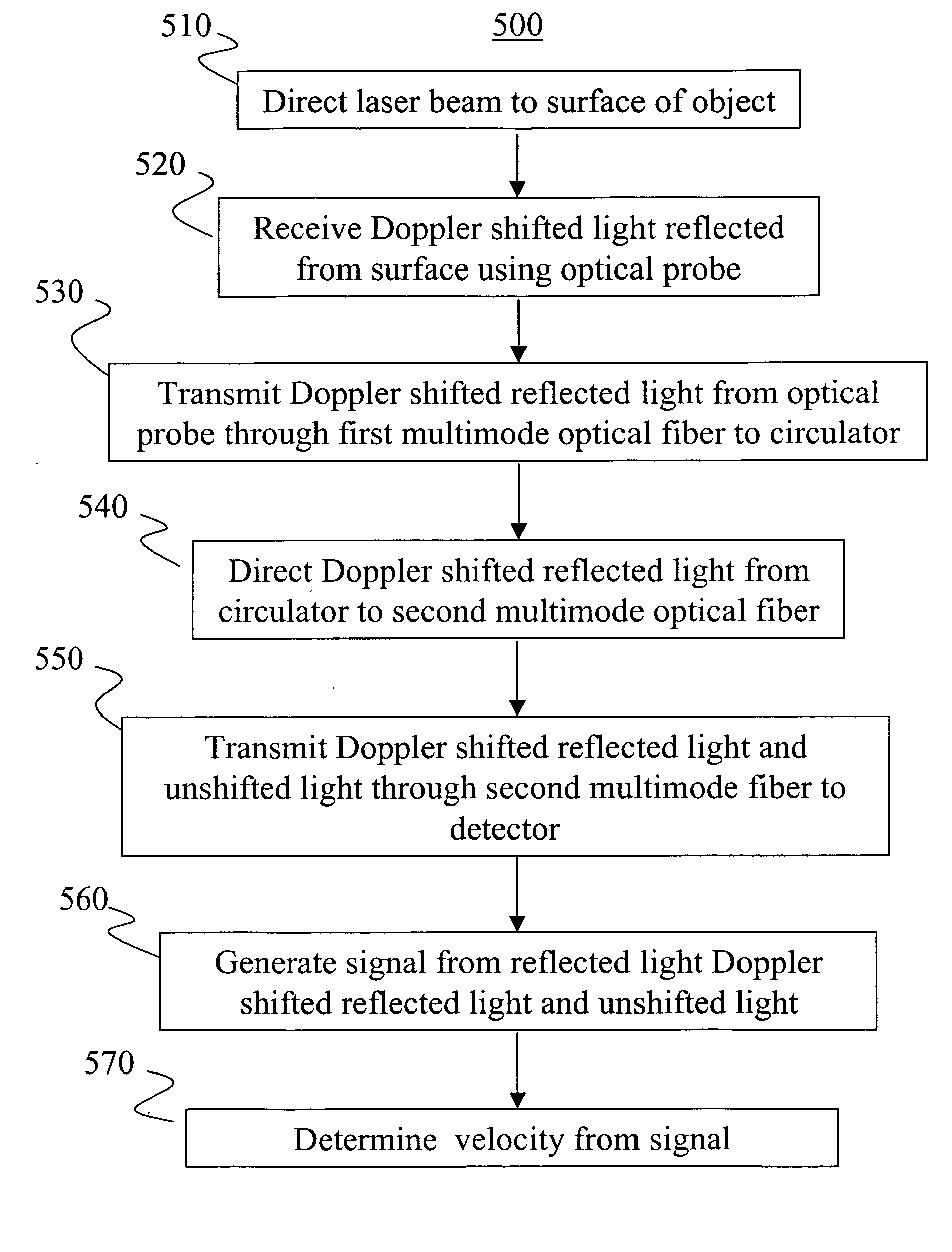
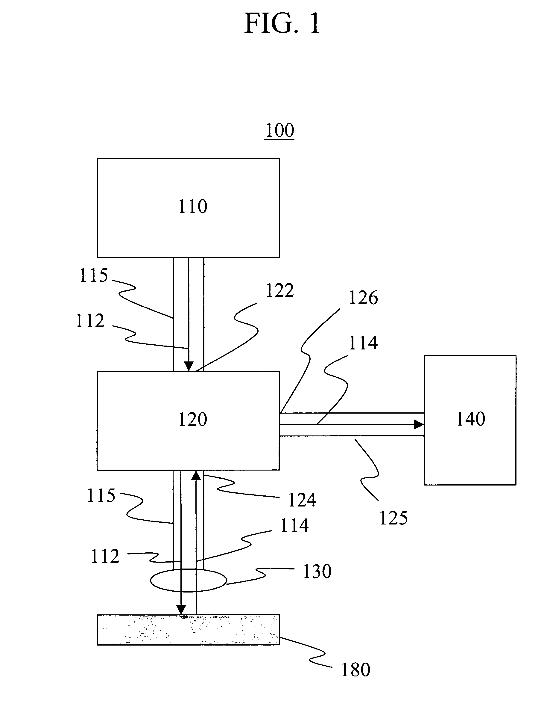
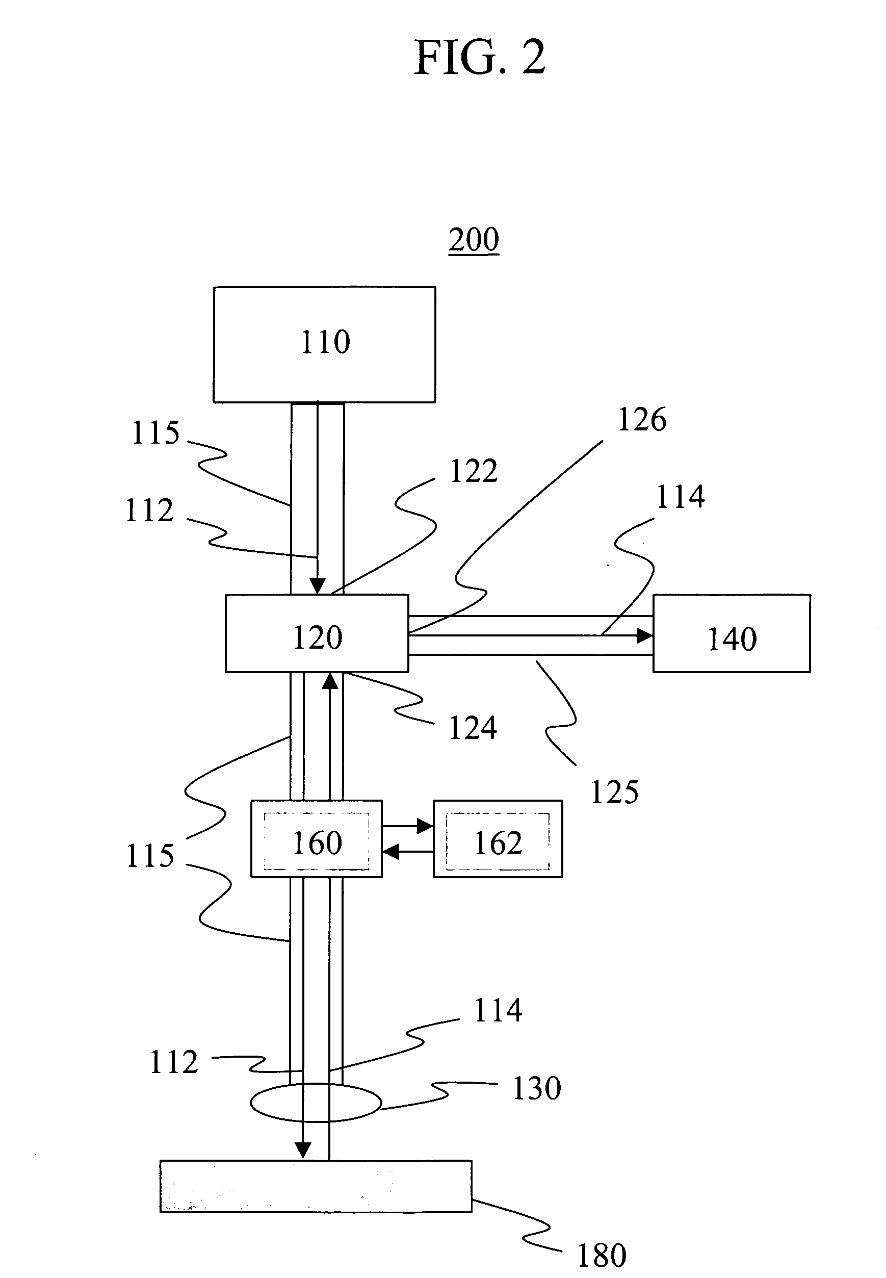
[0005]The present invention meets these and other needs by providing a laser velocimetry system that employs a low power laser. In one embodiment, the laser has a power of up to about 100 mW. Light from the laser, in one embodiment, is directed through a multimode optical fiber and an optical probe to a surface of a moving sample. Doppler shifted light from the surface is reflected back through the optical probe and multimode optical fiber to a circulator, which directs the light reflected from the surface to a second multimode optical fiber. Unshifted (i.e., non-Doppler shifted) light is also introduced into the optical signal path. The Doppler shifted reflected light and the unshifted light are then transmitted through the second multimode optical fiber to a detector, which converts the reflected light into an electronic signal. The electronic signal of the “beat”—i.e., the difference in frequency between the Doppler shifted light and unshifted light—may then be digitized by an analyzer and used to determine the velocity of the moving surface. A method of determining the velocity of a moving object is also described.

Problems solved by technology

Such techniques typically require instrumentation that is large in size, costly, and complicated to field.
In particular, lasers used in such techniques often must operate at high power.
Because of their large size and complexity, current velocimetry techniques cannot be easily adapted for applications where considerations such as weight, power, and size are critical.

Method used


Image

  • Laser velocimetry system
  • Laser velocimetry system
  • Laser velocimetry system

Examples


example 1

[0038]A laser velocimetry system such as that described hereinabove was constructed using the following components: a laser photodiode (JDS Uniphase Model CQF938 / 600) having a wavelength of 1550 nm; an optical circulator (Agiltron Part #OC-30511223) using a graded index multimode fiber; and a photodiode detector and amplifier (Miteq Model SCMR-50K6G-30-15-10-MM).

[0039]Using the above components, a moving metal foil was viewed with a bare fiber probe. The foil was viewed through the probe from a distance of several millimeters. Motion of the foil was induced by lightly tapping the foil. The data was obtained using the velocimetry system and the velocity of the foil was determined.

[0040]Samples of the data obtained from the experiment are shown in FIGS. 6, 7, and 8. The raw recorded data is shown in FIG. 6, and Figure FIG. 7 shows an expanded portion of FIG. 6 near the time of first motion. The velocities were then determined using the Short Time Fourier Transform method. The velociti...


PUM


Abstract

A laser velocimetry system that employs a low power laser. The laser has a power of up to about 100 mW. Light from the laser, in one embodiment, is directed through a multimode optical fiber and an optical probe to a surface of a moving sample. Doppler-shifted light from the surface is reflected back through the optical probe and multimode optical fiber to a circulator, which directs the light reflected from the surface to a second multimode optical fiber. Unshifted (i.e., non-Doppler shifted) light is also introduced into the optical signal path. The Doppler shifted reflected light and the unshifted light are then transmitted through the second multimode optical fiber to a detector, which converts the reflected light into an electronic signal. The electronic signal of the “beat” between the Doppler shifted light and unshifted light may then be digitized by an analyzer and used to determine the velocity of the moving surface. A method of determining the velocity of a moving object is also described.

Description

STATEMENT REGARDING FEDERAL RIGHTS[0001]This invention was made with government support under Contract No. DE-AC 52-06 NA 25396, awarded by the U.S. Department of Energy. The government has certain rights in the invention.BACKGROUND OF INVENTION[0002]The invention relates to the determination of the velocity of a moving sample. More particularly, the invention relates to an apparatus for determining such velocities. Even more particularly, the invention relates to an apparatus and method for determining such velocities using laser Doppler velocimetry.[0003]The measurement of the velocity of a moving surface is of interest in the field of hydrodynamics and studies of shock-related phenomena, such as shock-induced melting. Velocimetry techniques, such as Photon Doppler Velocimetry (also referred to herein as “PDV”), Fabry-Perot interferometry, and Velocity Interferometry System for Any Reflector (also referred to herein as “VISAR”) typically rely on interferometry on Doppler shifted l...

Claims


Application Information

Patent Timeline
Patent Type & Authority Applications(United States)
IPC IPC(8): G01P3/36
CPCG01P3/366G01S17/58G01S7/4818
Inventor HOLTKAMP, DAVID B.TABAKA, LEONARD J.
Owner RGT UNIV OF CALIFORNIA
Why Eureka
Try Eureka