Method and system for looping back traffic in qiq ethernet rings and 1:1 protected PBT trunks

a technology of ethernet rings and trunks, applied in the field of ethernet, can solve the problems of reducing the service life of ethernet rings, affecting the deployment of large (metro area) ethernet rings, and general unsuitability of standard ethernet (ieee 802.3) for network topologies, etc., and achieve the effect of reducing the delay

Inactive Publication Date: 2008-04-24
RPX CLEARINGHOUSE
View PDF16 Cites 94 Cited by
  • Summary
  • Abstract
  • Description
  • Claims
  • Application Information

AI Technical Summary

Benefits of technology

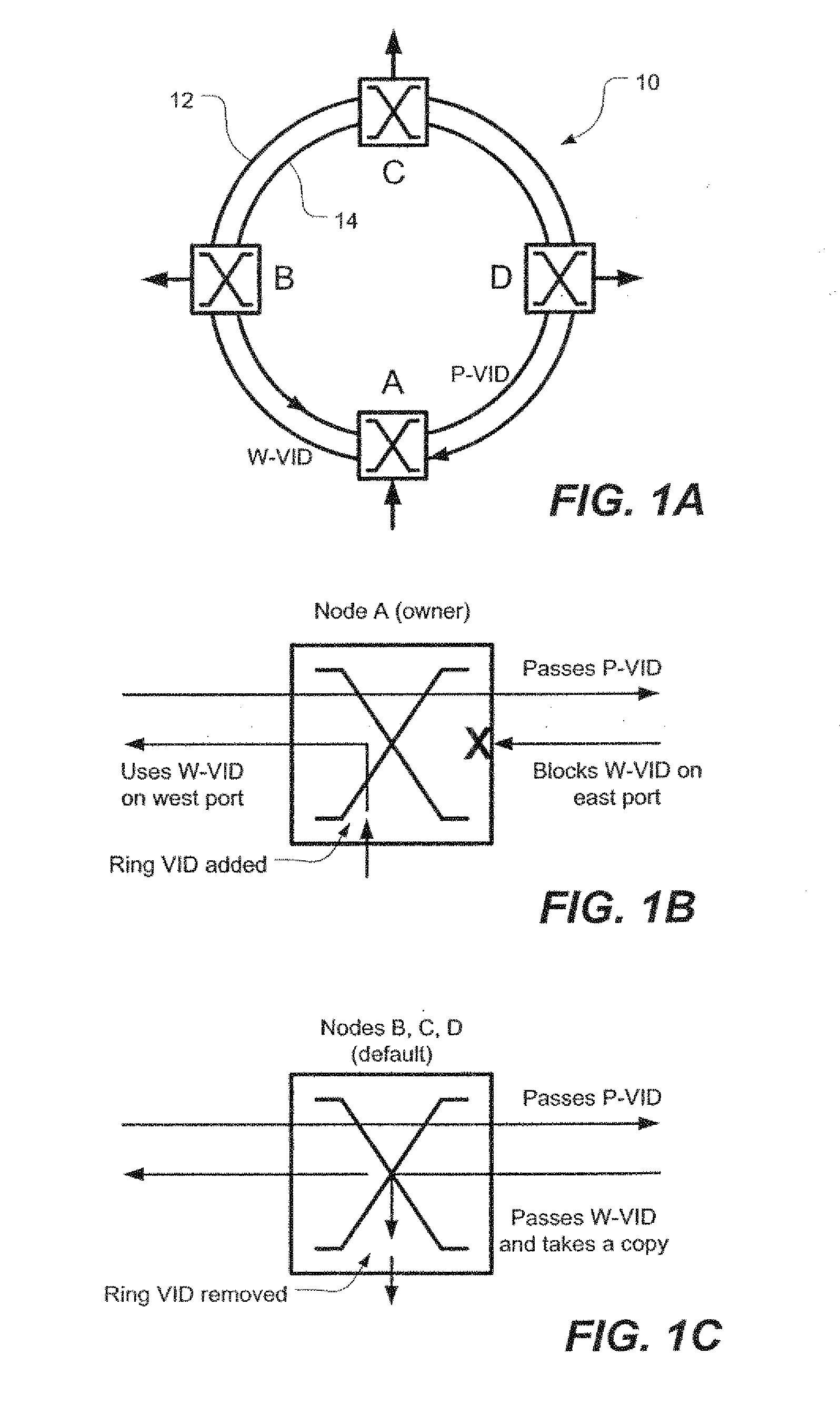
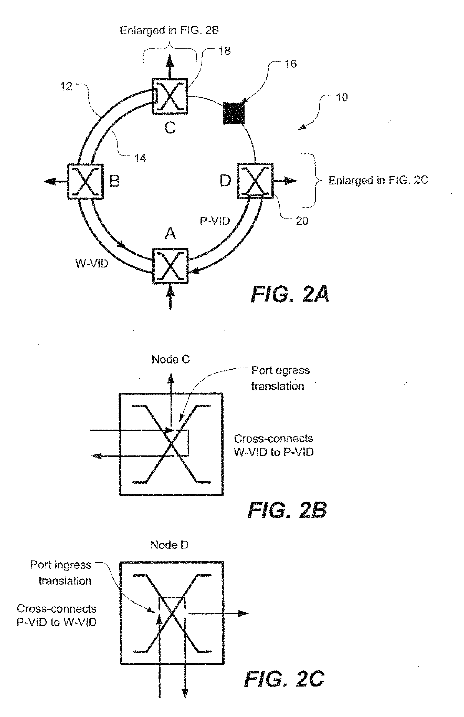
[0010] An aspect of the present invention is to provide a simple, resilient and high-speed virtual ring for frame-based traffic such as Ethernet that redresses one or more of the deficiencies in the prior art as described above. The resilient virtual ring has a plurality of nodes interconnected by working and protection virtual paths. The virtual ring will have a working path in which traffic flows in one direction, and a protection path in which the traffic flows in the opposite direction. It is conceivable to have multiple virtual rings which have the same routing for the working path and for the protection paths. It is similarly possible to envision multiple virtual rings where the routing is a mirror image, the routing of one or more rings protection path corresponding to the routing of the working path or path of other rings. It is similarly possible to consider a node to simultaneously be a ring node on several topologically disjoint rings at the same time. Each virtual ring implements a unique Ethernet broadcast domain. Each virtual ring is implemented via configured connectivity for a set of VLANs. Traffic upon insertion into the ring is tagged using ring tags which serve to identify the originating station on the ring and are associated with the specific broadcast domain. These tags are removed when the traffic leaves the ring. For Ethernet, these ring tags are VLAN IDs (VIDs) and the insertion of VLAN tags is described in IEEE standard 802.1ad. When traffic enters the ring, the ingress node tags the traffic with a working-path VID which also identifies the entry point to the ring.
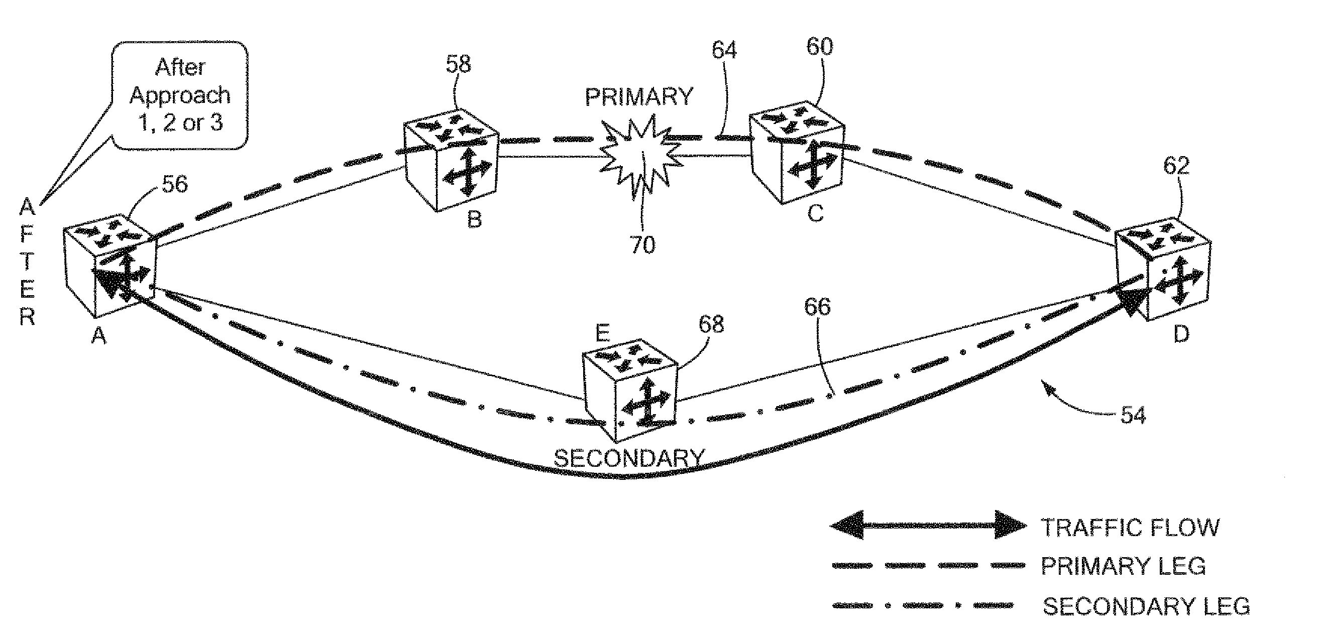
[0019] Another aspect of the invention provides a method for reducing delay in a fast protection switching network caused by the looping back of transmitted packets. The method includes detecting occurrence of a loopback condition due to a failure on the primary path, halting transmission of packets between a source node and the destination node on the primary path, and starting transmission of the packets between the source node and the destination node on a secondary path.

Problems solved by technology

Because of its “flood-and-learn” nature, standard Ethernet (IEEE 802.3) is generally unsuitable for network topologies where there is more than one path between any two nodes.
The existence of a parallel path creates a loop around which the Ethernet frames circle endlessly, thus overburdening the network.
Deployment of large (metro area) Ethernet rings is hindered, however, by the fact that Ethernet rings are prone to endlessly loop unless protocols such as IEEE 802.1D Spanning Tree Protocol (STP) or IEEE 802.1W Rapid Reconfiguration are used to detect and disable parallel branches that create loops.
While Spanning Tree Protocol and Rapid Reconfiguration can eliminate loops on Ethernet rings, these protocols introduce recovery lags in the order of tens of seconds, i.e. the time to recover from a fault in the ring is unacceptably high for customers who expect seamless connectivity and undetectable fault correction.
Thus, even if all the other components of the Ethernet switches are capable of handling higher rates, as is currently achievable, the ring MAC-PHY chip limits the overall bit-rate of the ring.
An additional shortcoming of current network topologies is the unwanted time delay that occurs when, due to a fault in the system, transmitted data packets are returned or “looped back” to the originating source node.
While a secondary path is used to handle traffic that can no longer be delivered to its destination via the primary path due to the fault, significant delay time is accumulated due to the time that it takes for traffic to travel to the point of failure and then travel back to its originating node.

Method used


Image

  • Method and system for looping back traffic in qiq ethernet rings and 1:1 protected PBT trunks
  • Method and system for looping back traffic in qiq ethernet rings and 1:1 protected PBT trunks
  • Method and system for looping back traffic in qiq ethernet rings and 1:1 protected PBT trunks

Examples


Embodiment Construction

[0043] It will be appreciated by persons skilled in the art that the present invention is not limited to what has been particularly shown and described herein above. In addition, unless mention was made above to the contrary, it should be noted that all of the accompanying drawings are not to scale. A variety of modifications and variations are possible in light of the above teachings without departing from the scope and spirit of the invention, which is limited only by the following claims.

[0044] In general, and as will be elaborated below with respect to the specific embodiments illustrated in FIGS. 1-6, the present invention provides both a resilient, virtual ring for frame-based traffic such as, preferably, Ethernet as well as a method of routing frame-based (e.g. Ethernet) traffic over a resilient, virtual ring. Although the embodiments described below are implemented in Ethernet, it should be understood that the invention could be applied to other frame-based networks.

[0045]...


PUM


Abstract

A resilient virtual Ethernet ring has nodes interconnected by working and protection paths. If a span fails, the two nodes immediately on either side of the failure are cross-connected to fold the ring. Working-path traffic is cross-connected onto the protection path at the first of the two nodes and is then cross-connected back onto the working path at the second of the two nodes so that traffic always ingresses and egresses the ring from the working path. A traffic originating node, upon determining that transmitted packets are being looped back due to a fault on a primary path, is adapted to switch transmission of data packets from the primary path to a secondary path.

Description

CROSS-REFERENCE TO RELATED APPLICATION [0001] This application is a continuation-in-part-of patent application Ser. No. 11 / 477,975, filed Jun. 29, 2006, entitled Q-IN-Q ETHERNET RINGS, the entirety of which is incorporated herein by reference.STATEMENT REGARDING FEDERALLY SPONSORED RESEARCH OR DEVELOPMENT [0002] n / a FIELD OF THE INVENTION [0003] The present invention relates generally to Ethernet and, in particular, to Ethernet rings for Metro Area Networks and to switching networks that significantly reduce the delay associated with looped back traffic due to network faults. BACKGROUND OF THE INVENTION [0004] Because of its “flood-and-learn” nature, standard Ethernet (IEEE 802.3) is generally unsuitable for network topologies where there is more than one path between any two nodes. The existence of a parallel path creates a loop around which the Ethernet frames circle endlessly, thus overburdening the network. Therefore, Ethernet is best suited to a tree topology rather than a ring...

Claims


Application Information

Patent Timeline
Patent Type & Authority Applications(United States)
IPC IPC(8): H04L12/26H04L45/24H04L45/28
CPCH04L41/0668H04L45/28H04L45/22
Inventor SKALECKI, DAREKALLAN, DAVID I.BRAGG, NIGEL L.HOLNESS, MARC
Owner RPX CLEARINGHOUSE
Why Eureka
Try Eureka