
Distal cooling distribution system for a medical device

Active Publication Date: 2008-04-24
MEDTRONIC CRYOCATH LP
View PDF37 Cites 4 Cited by
  • Summary
  • Abstract
  • Description
  • Claims
  • Application Information

AI Technical Summary

Benefits of technology

[0007]The present invention advantageously provides a method and system for accommodating and managing lengths of conduit in a medical device to prevent unwanted kinking and / or damage to components, while further facilitating and easing overall use of the device. In addition, he present invention advantageously ensure the desired location and / or placement of moving parts of a medical device during a particular sequence of operation of the device.

Problems solved by technology

Regardless of the particular approach, the expansion / inflation of the balloon may result in alternating periods of slack and tension in the conduits providing fluid flow, electrical connections, and the like, which can cause axial and longitudinal movement of the conduits.
Such movement may result in the undesired kinking and / or tangling of multiple conduits of a device, whereby the kinking may degrade or prevent the performance of the device, causing a reduction in the overall effectiveness and / or usability of the device for certain medical procedures.
Should such axial displacement occur during an inflation sequence, there may be a risk that inflation fluid will be directed towards an undesirable portion of the balloon and / or surrounding structures of the medical device.
Moreover, should the inflation fluid perform an additional function, such as providing a particular thermal condition at a specific portion of the balloon, then axial displacement of the inflation tube may disrupt and / or reduce the effectiveness or achievement of the desired condition.

Method used


Image

  • Distal cooling distribution system for a medical device
  • Distal cooling distribution system for a medical device
  • Distal cooling distribution system for a medical device

Examples


Embodiment Construction

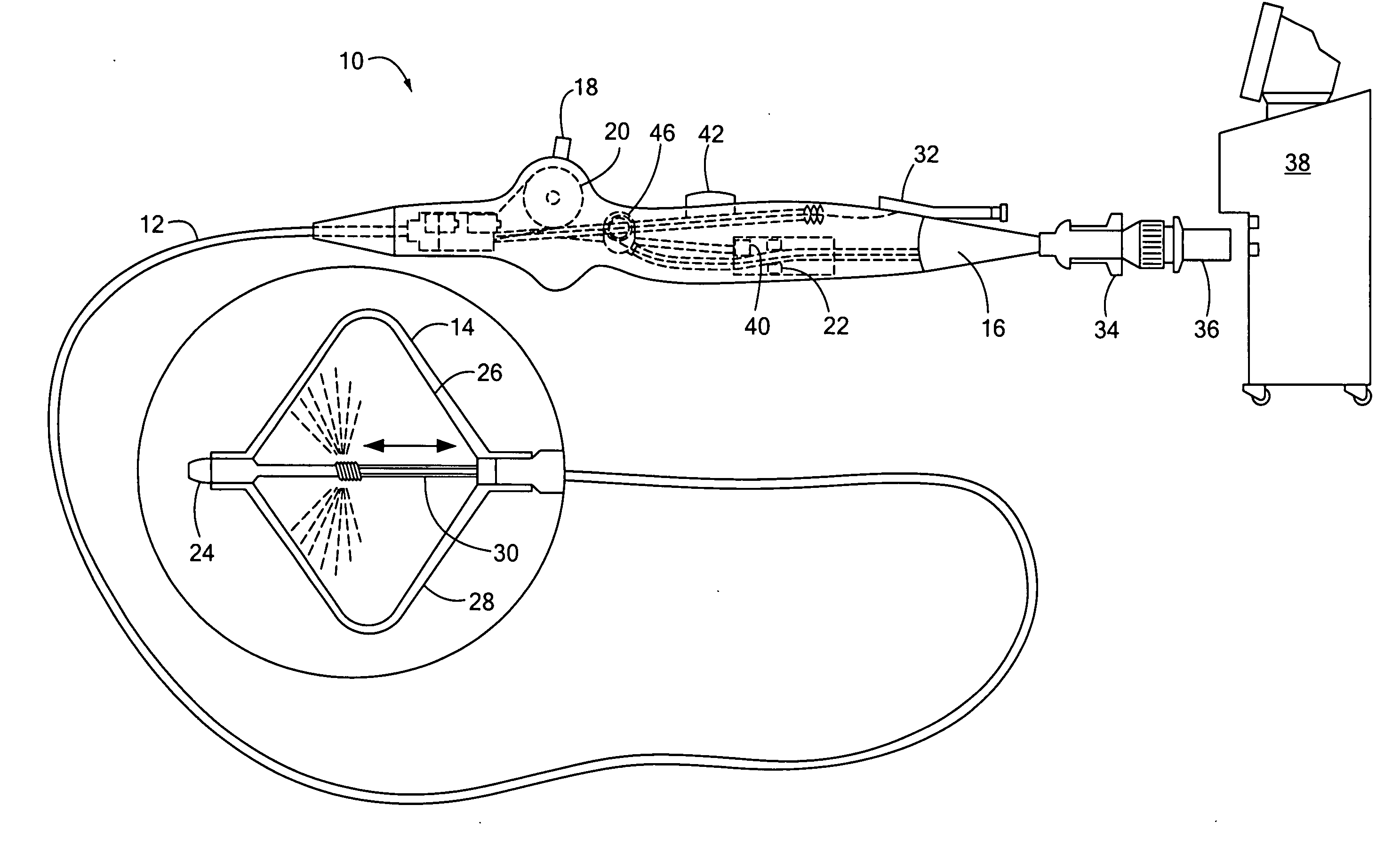
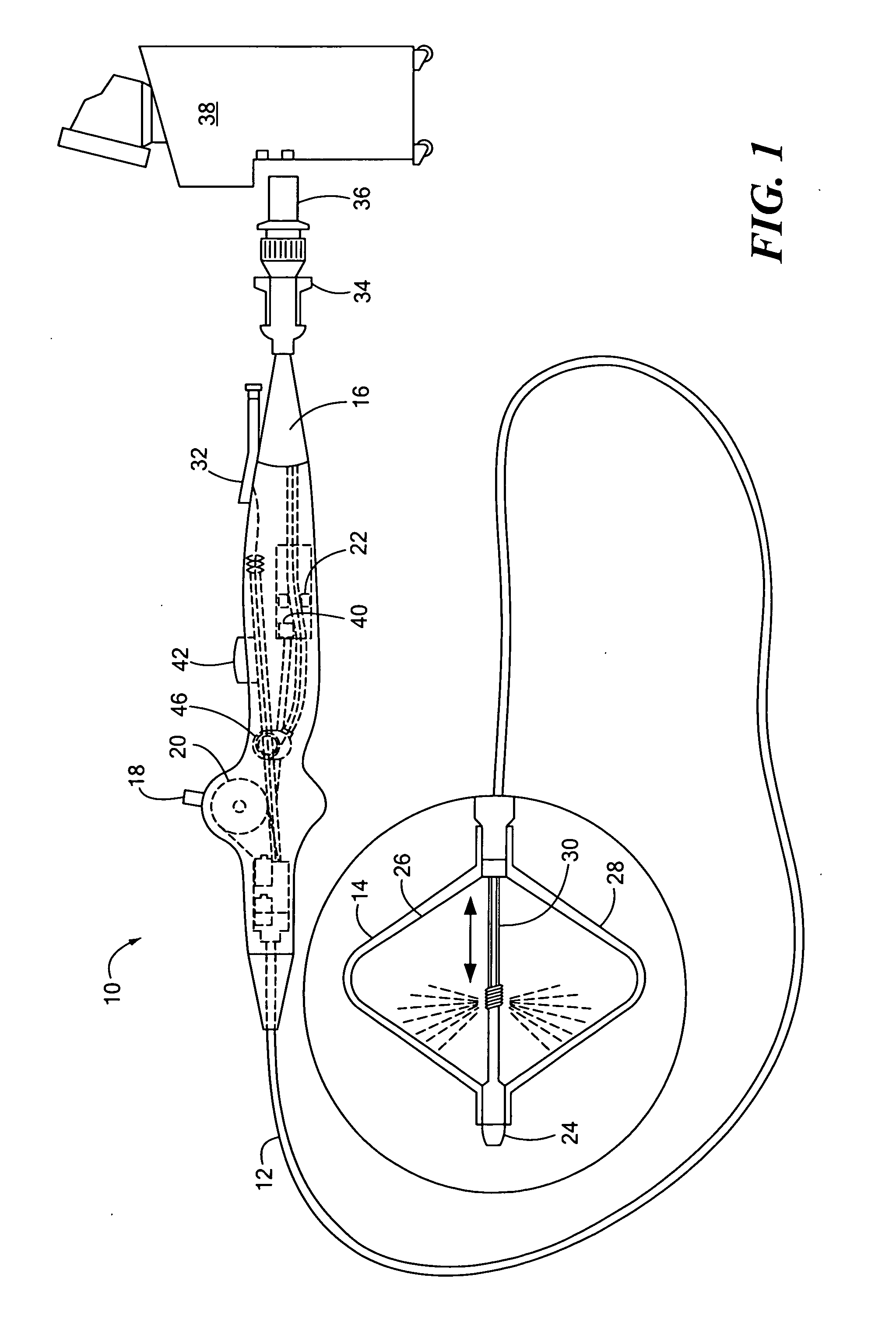
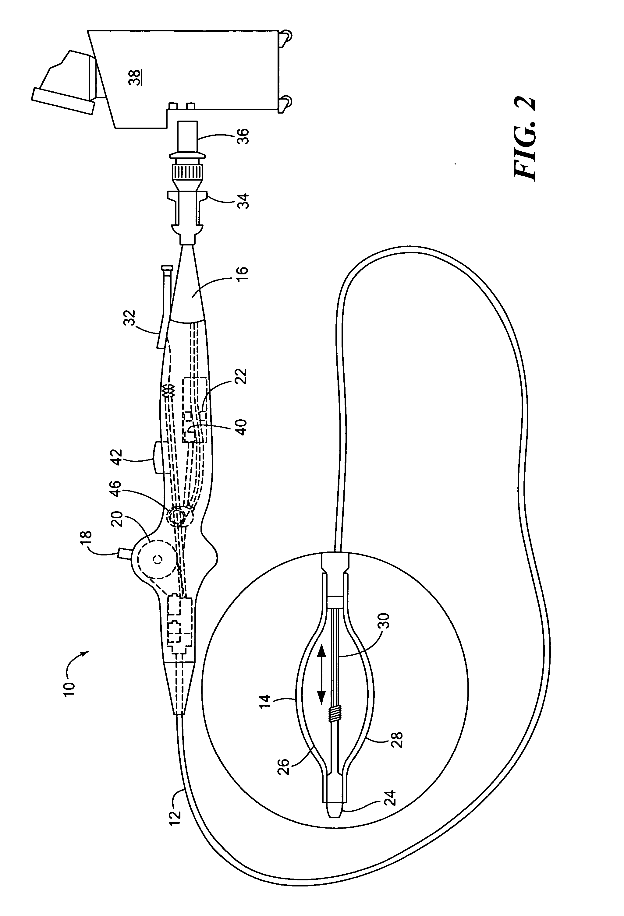
[0018]FIGS. 1 and 2 illustrate an exemplary system for performing a surgical procedure, including ablation, dilation, or the like. The system includes a medical device 10, which may include an elongate, highly flexible catheter that may be suitable for passage through the vasculature. The catheter may include a catheter body 12 having a distal end with an expandable element 14 at or proximal to the distal end. The distal end and the expandable element 14 are shown magnified and are described in greater detail below. The catheter body 12 has a proximal end that is mated to a handle 16, where the handle 16 may include an element such as a lever or knob 18 for manipulating the catheter body 12 and / or additional components of the medical device 10. For example, a pull wire with a proximal end and a distal end may have its distal end anchored to the catheter at or near the distal end. The proximal end of the pull wire may be anchored to an element such as a cam 20 in communication with a...


PUM


Abstract

The present invention may include a medical device having a handle, a catheter coupled to the handle, and an expandable element coupled to the catheter. The medical device may also include first and second elongate bodies that traverse a length of the handle and catheter. A housing may be disposed within the handle, with the housing defines a first opening able to receive a portion of the first elongate body, a second opening able to receive a portion of the second elongate body, and a third opening opposite the first and second openings able to receive a portion of both the and second elongate bodies. A separation element may be disposed within the housing, with the separation element defining a path able to receive a portion of the second elongate body, and whereby a portion of the first elongate body forms a loop around the separation element.

Description

REFERENCE TO RELATED APPLICATION[0001]This application is a continuation-in-part of pending Utility Patent application Ser. No. ______, filed Jun. 05, 2006, by Yixin Hu, et al., entitled SERVICE LOOP, the entirety of which is incorporated herein by reference.STATEMENT REGARDING FEDERALLY SPONSORED RESEARCH OR DEVELOPMENT[0002]n / aFIELD OF THE INVENTION[0003]The present invention provides an apparatus for accommodating and managing lengths of conduit in a medical device, as well as for maintaining a spatial relationship between movable components of the medical device.BACKGROUND OF THE INVENTION[0004]Medical devices used in surgery for performing ablation, dilation, and the like often include multiple conduits and connectors for providing both fluid flow and electrical connections between the device and a fluid supply and / or control console, as well as providing for steering or navigation of the device over a guidewire. In particular, some surgical procedures involve the expansion or ...

Claims


Application Information

Patent Timeline
IPC IPC(8): A61M25/10A61M29/02A61M25/00A61M31/00A61F2/958
CPCA61B18/02A61B2018/0212A61B2018/0022A61B2017/22051A61M25/1025A61M2025/0004A61M2025/0175A61M2025/1061
Inventor HU, YIXINTZONEV, VLADIMIRMIHALIK, TERESA ANNTHIBAULT, BENOITWITTENBERGER, DANLANE, MIRIAMPETRE, CRISTIAN
Owner MEDTRONIC CRYOCATH LP
Learn More