Biodegradable Closure Device

a technology of closure device and biodegradable material, which is applied in the field of biodegradable closure device, can solve the problems of reducing the blood flow risk, requiring hours without the involvement of the patient, and hematoma risk, so as to prevent bleeding

Inactive Publication Date: 2008-04-24
BY PASS
View PDF2 Cites 57 Cited by
  • Summary
  • Abstract
  • Description
  • Claims
  • Application Information

AI Technical Summary

Benefits of technology

[0009]An aspect of some embodiments of the invention concerns a biodegradable balloon which is expanded inside the body, exerting pressure on body tissue. In some embodiments of the invention, the balloon exerts pressure on the wall of a blood vessel which has a hole in it, such as a puncture made for catheterization. The pressure exerted by the balloon substantially prevents bleeding from the hole, and the balloon remains in place and eventually disinte

Problems solved by technology

This method has a few drawbacks, as it is time consuming, poses a risk of hematoma and risk of reduction in blood flow due to the manual pressure, and requires hours without motion of the involved patient limb after the pressure is removed.
However, since the

Method used


Image

  • Biodegradable Closure Device
  • Biodegradable Closure Device
  • Biodegradable Closure Device

Examples


Embodiment Construction

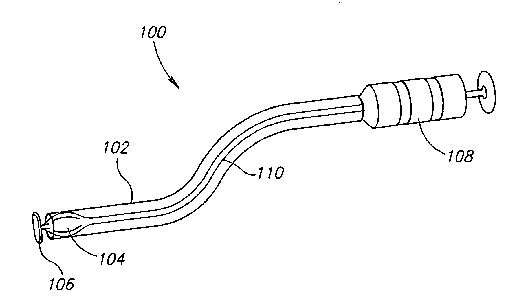
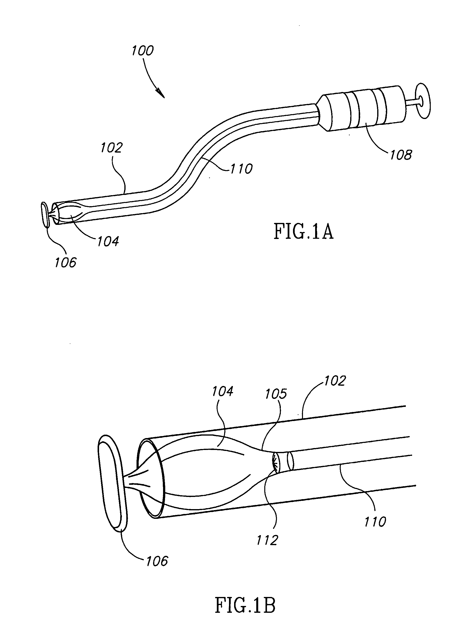
[0071]FIG. 1A shows a system 100 for hemostasis of a hole in a blood vessel wall. A flexible tube 102 has a balloon 104 inside it near the distal end, and there is a rod-shaped anchor 106, just past the distal end of flexible tube 102, attached to balloon 104. Balloon 104 is shown in a collapsed state. A syringe 108 filled with saline solution is located on the proximal end of tube 102, and is used to expand the balloon through a filling tube 110, which runs through tube 102.

[0072]Alternatively, there is no tube 102, and system 100 consists of balloon 104, anchor 106, filling tube 110, and syringe 108. Having a tube 102 around the filling tube and balloon has the potential advantage of protecting these parts, and making it easier to place them into a blood vessel as will be described below in FIG. 3, for example by providing greater stiffness.

[0073]Alternatively, instead of balloon 104, there is an expandable biodegradable sponge.

[0074]FIG. 1B is a more detailed view of the distal e...


PUM


Abstract

A biodegradable balloon adapted to exert pressure on a hole formed in a lumen in the body when placed adjacent to the hole, inside the body, and expanded, and adapted to remain in place thereafter and to be absorbed by the body.

Description

RELATED APPLICATIONS[0001]The present application claims the benefit under 119 (e) of U.S. Provisional Application No. 60 / 529,092 filed on Dec. 15, 2003, the disclosure of which is incorporated herein by reference.FIELD OF THE INVENTION[0002]The field of the invention is devices which exert pressure on tissue inside the body, in particular to stop bleeding from holes in blood vessels.BACKGROUND OF THE INVENTION[0003]Percutaneous transluminal coronary angioplasty and other medical interventions involve access into the vascular system. In many cases, the treatment or diagnostic device, such as catheter and balloon angioplasty device, is introduced into the vascular system via a catheter introducer / sheath, cannula or the like, which occasionally are of relatively large diameter to enable the passage of the treatment / diagnostic device through them. At the end of the intravascular procedure, following removal of catheter sheath / cannula, the blood vessel aperture should be closed and seal...

Claims


Application Information

Patent Timeline
IPC IPC(8): A61M29/00A61BA61B17/00
CPCA61B17/0057A61B2017/00539A61B2017/00659A61B2017/00637A61B2017/00557
Inventor BEYAR, MORDECHAYGLOBERMAN, ORENLOSHAKOVE, AMIRGOLDBERG, ERANKILEMNIK, IDO J.
Owner BY PASS
Why Eureka
Try Eureka