Apparatus And Method For Calculating Aiming Point Information

a technology of aiming point information and apparatus, which is applied in the field of target acquisition, can solve the problems of insufficient skill of the shooter and insufficient consistency of ammunition, and conventional telescopic target acquisition devices are not generally useful at long ranges in excess of 400-800 yards, and conventional target acquisition devices generally fall short when extreme accuracy is desired

Inactive Publication Date: 2008-05-01
HORUS VISION
View PDF69 Cites 132 Cited by
  • Summary
  • Abstract
  • Description
  • Claims
  • Application Information

AI Technical Summary

Benefits of technology

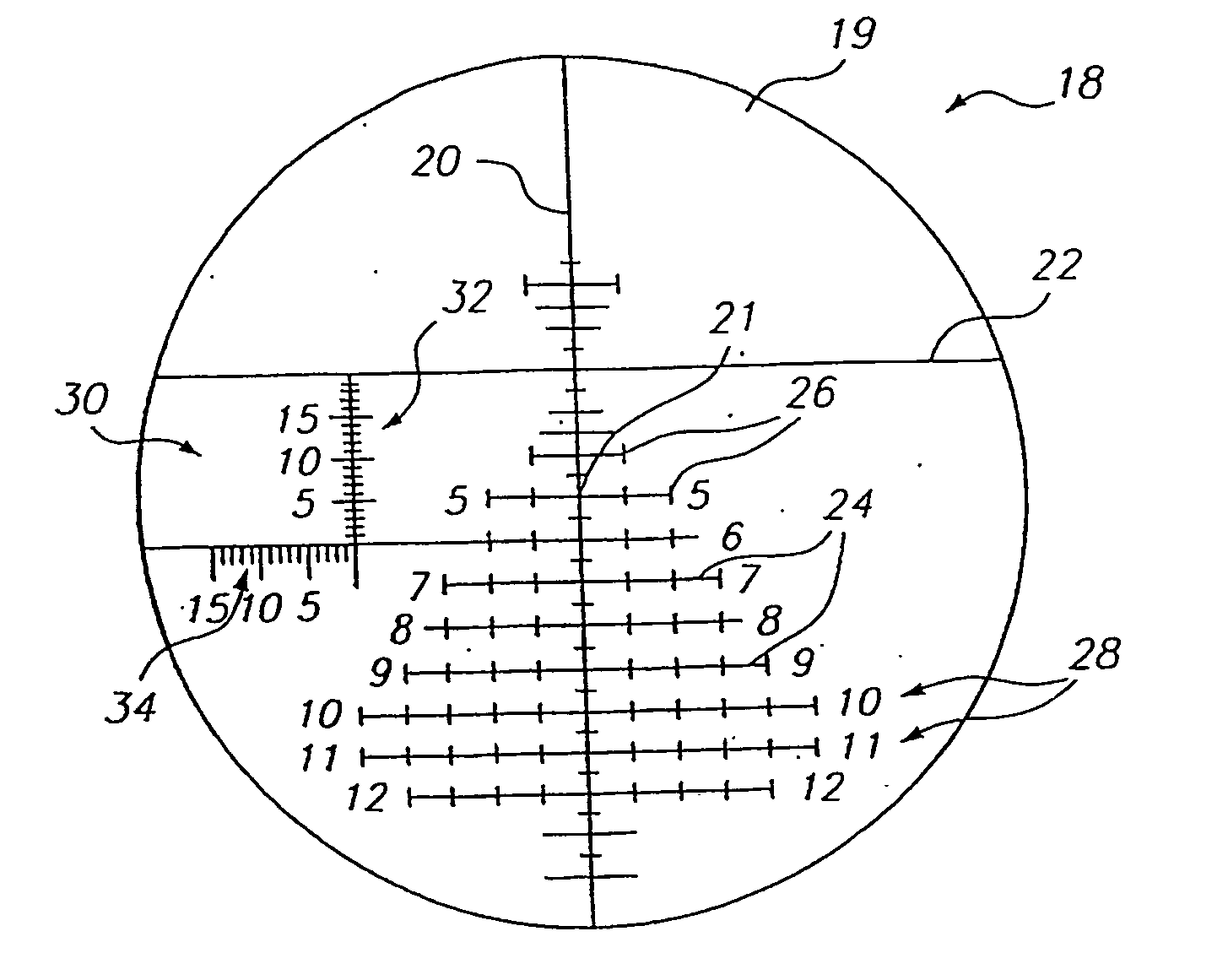
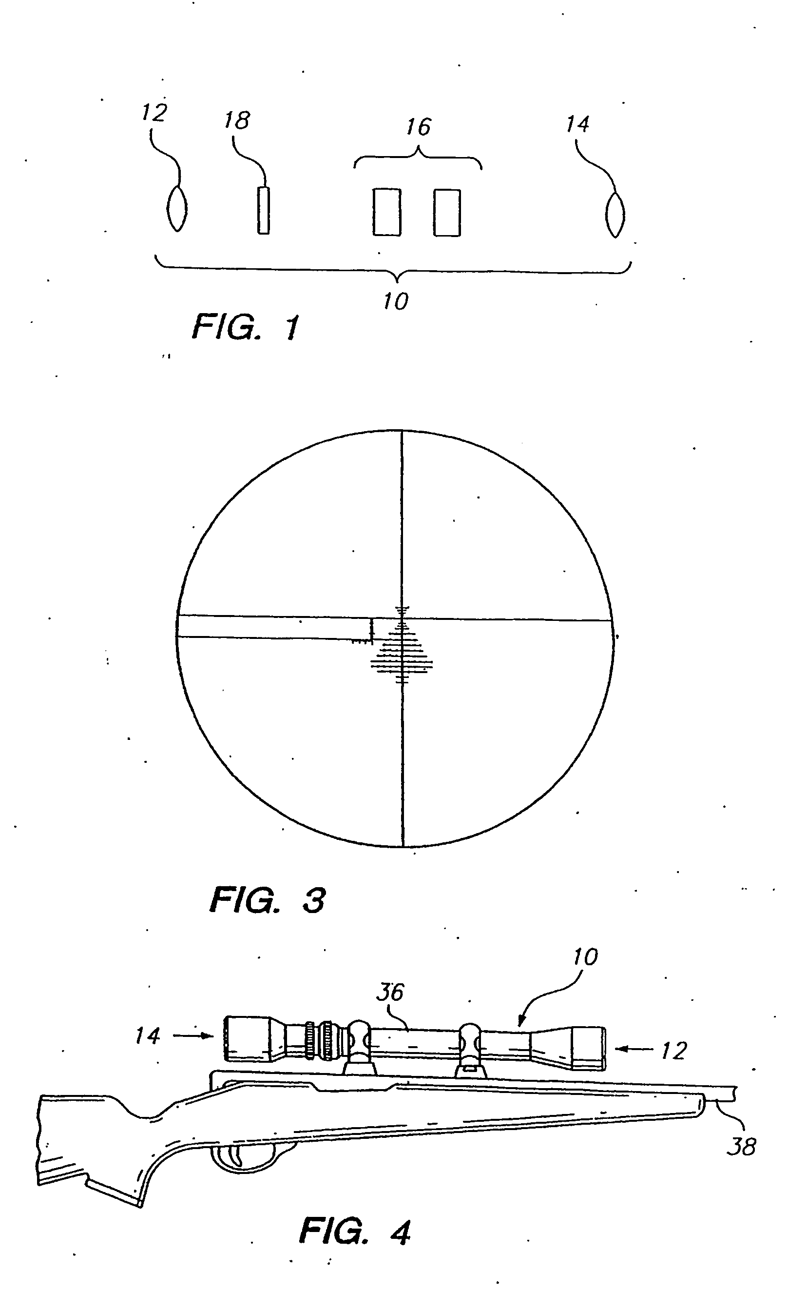
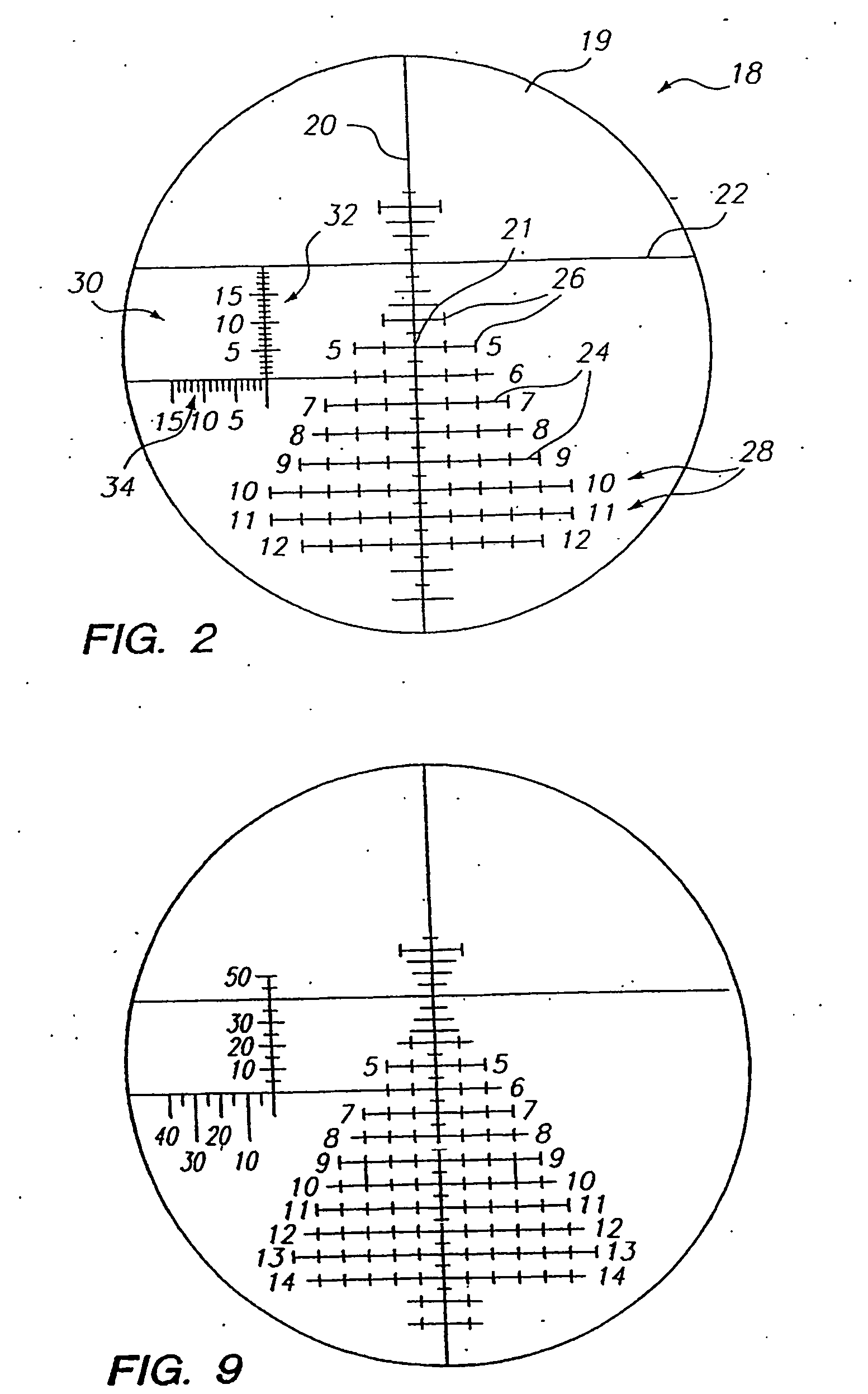
[0014]The present invention provides reticles that provide means for selecting secondary aiming points that accurately target an intended target at any desired range, including extreme distances. In particular, the reticles of the present invention provide markings or other indications that allow a user, for example, to associate a first aiming point of the reticle with an intended target (e.g., the aiming point created by the cross-section of primary vertical and horizontal cross-hairs), and to identify a second aiming point (e.g., identified by a generated aiming dot, an electronic aiming dot, or an aiming point created by secondary vertical and / or horizontal cross-hairs) that represents a point to insure an accurate shot to hit the target.

Problems solved by technology

At very long ranges, in excess of 500 yards, however, the skill of the shooter and the consistency of the ammunition is often not enough to insure that the shooter will hit the target.
In addition, conventional telescopic target acquisition devices are not generally useful at long ranges in excess of 400-800 yards.
At close ranges less than 100 yards conventional target acquisition devices generally fall short when extreme accuracy is desired.
Modifications to this basic system have not, thus far, enabled a skilled shooter firing at long ranges to acquire and hit a target quickly and reliably, regardless of the weapon used (assuming always that the firearm is capable of reaching a target at the desired long range).
Apparently because of the innate variation in the height of any given individual from that used to produce the reticle, and the resulting inaccuracy which that would produce at long ranges, Critchett's scope was only useful to 600 yards.
However, like Critchett, the usefulness of Rubbert for shooting other targets of varying size at long range is doubtful.
Leatherwood's scope, like the others discussed above, has limited utility at long ranges because it is designed with a specific size target in mind, and would therefore be inaccurate when used with targets of widely varying size, and also because at long range the scope may not be able to move sufficiently in relation to the barrel (i.e., may be obstructed by the gun barrel).
However, having to rotate a secondary reticle to locate an appropriate target shape in order to determine the range is time consuming and undesirable, since it takes the shooter's attention away from the target.
However, since a laser rangefinder emits light, there is always the possibility that the beam from a laser rangefinder could be detected by an individual with special equipment, revealing the position of the shooter, causing a live target to move, or other undesirable consequences for the rifleman using the laser before the shot can be taken.
Furthermore, a laser rangefinder includes complex electronics which must be handled with care.
The additional weight is a burden, and the possibility exists that power source could fail or become exhausted through use, causing the rangefinder to cease working.

Method used


Image

  • Apparatus And Method For Calculating Aiming Point Information
  • Apparatus And Method For Calculating Aiming Point Information
  • Apparatus And Method For Calculating Aiming Point Information

Examples


Embodiment Construction

[0131]The present invention relates to target acquisition and related devices, and more particularly to telescopic gunsights and associated equipment used to achieve shooting accuracy at, for example, close ranges, medium ranges and extreme ranges at stationary and moving targets. Certain preferred and illustrative embodiments of the invention are described below. The present invention is not limited to these embodiments.

[0132]As used herein, the term “firearm” refers to any device that propels an object or projectile, for example, in a controllable flat fire, line of sight, or line of departure, for example, handguns, pistols, rifles, shotgun slug guns, muzzleloader rifles, single shot rifles, semi-automatic rifles and fully automatic rifles of any caliber direction through any media. As used herein, the term “firearm” also refers to a remote, servo-controlled firearm wherein the firearm has auto-sensing of both position and directional barrel orientation. The shooter is able to po...


PUM


Abstract

The present invention relates to target acquisition and related devices, and more particularly to telescopic gunsights and associated equipment used to achieve shooting accuracy at, for example, close ranges, medium ranges and extreme ranges at stationary and moving targets.

Description

RELATED APPLICATIONS[0001]This application is a continuation-in-part of co-pending U.S. patent application Ser. No. 10 / 716,184 filed 12 Nov. 2003, which is a continuation-in-part of U.S. patent application Ser. No. 10 / 092,921 filed 6 Mar. 2002, now U.S. Pat. No. 6,681,512, which is a continuation-in-part of U.S. patent application Ser. No. 09 / 519,124 filed 6 Mar. 2000, now U.S. Pat. No. 6,453,595, which is a continuation-in-part of U.S. patent application Ser. No. 09 / 129,729 filed 5 Aug. 1998, now U.S. Pat. No. 6,032,374, which is a continuation-in-part of U.S. patent application Ser. No. 08 / 986,458 filed 8 Dec. 1997, now U.S. Pat. No. 5,920,995. Application Ser. No. 10 / 716,184 also claims priority to International Patent Application PCT / US02 / 18490, filed 10 Jun. 2002, which claims priority to U.S. patent application Ser. No. 09 / 882,767, filed 14 Jun. 2001, now U.S. Pat. No. 6,516,699, each of which is herein incorporated by reference in their entireties.FIELD OF THE INVENTION[0002]...

Claims


Application Information

Patent Timeline
Patent Type & Authority Applications(United States)
IPC IPC(8): F41G1/38F41GF41G1/473G02B23/14G02B27/32
CPCF41G1/38F41G1/473F41G3/06F41G1/387G02B23/14G02B27/32F41G3/08
Inventor SAMMUT, DENNIS J.CHAO, LAWRENCE
Owner HORUS VISION
Why Eureka
Try Eureka