Releasing mechanism and leveling apparatus

a technology of releasing mechanism and leveling apparatus, which is applied in the direction of metal rolling arrangement, metal-working feeding device, manufacturing tools, etc., can solve the problems of large noise generation, inability to adapt the release operation in such a way, and relatively long delay time, so as to improve the working environment, reduce noise, and good response

Active Publication Date: 2008-05-01
AIDA ENG LTD
View PDF6 Cites 20 Cited by
  • Summary
  • Abstract
  • Description
  • Claims
  • Application Information

AI Technical Summary

Benefits of technology

[0010]The present invention has been made in view of the above descried situations and has as an object to provide a release mechanism that can perform, even with a relatively simple structure, release operations with good response and low noise while improving the working environment. Another object of the present invention is to provide a leveling apparatus that can perform an opening operation that satisfactorily allows to perform work threading and maintenance as well as a release operation as described above even with a relatively simple structure.

Problems solved by technology

H05-70719 mentioned above, the release operation is performed using a cylinder in synchronization with press work that is performed at a relatively short cycle time, and accordingly a large noise is generated upon switching of an electromagnetic valve and / or upon collision occurring at cylinder ends.
In the case where a cylinder is used, there is a relatively long delay time since a clamp signal for causing the straightener feeder to terminate the releasing state and clamp the work is generated until the operation pressure actually reaches a predetermined level.
For this reason, it is not possible to adapt the release operation in such a way as to satisfactorily meet demands for increases in the number of strokes of press work per unit time (or increases in press work speed).
Accordingly, it is difficult to open the rolls to a large extent.
This disadvantageously leads to an increase in the size and complexity of the apparatus and causes various problems in terms of cost and ease of installation, assembly and maintenance of the apparatus.

Method used


Image

  • Releasing mechanism and leveling apparatus
  • Releasing mechanism and leveling apparatus
  • Releasing mechanism and leveling apparatus

Examples


Embodiment Construction

[0048]In the following, embodiments of the present invention will be described with reference to the accompanying drawings. It should be understood that the embodiments described in the following are intended only to illustrate the present invention and are not intended to limit the present invention.

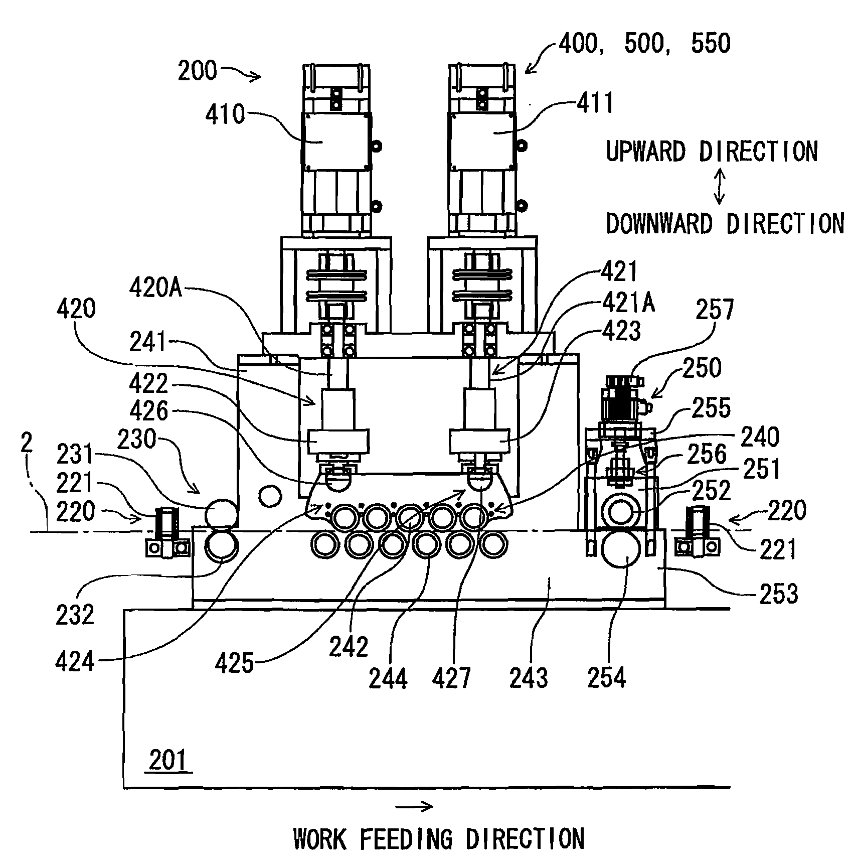
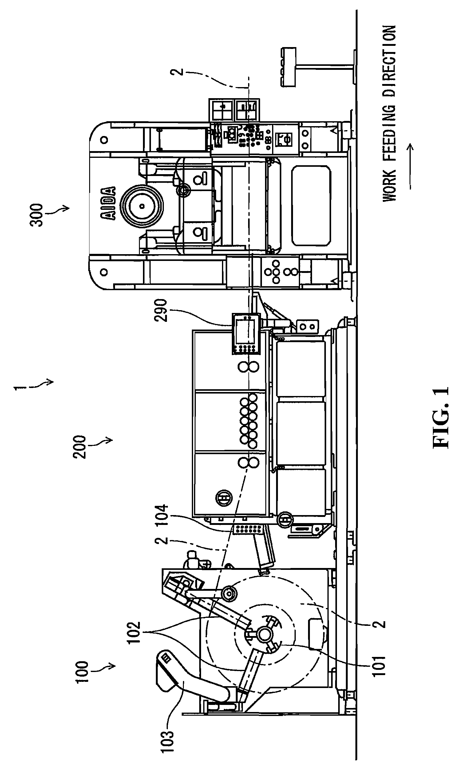
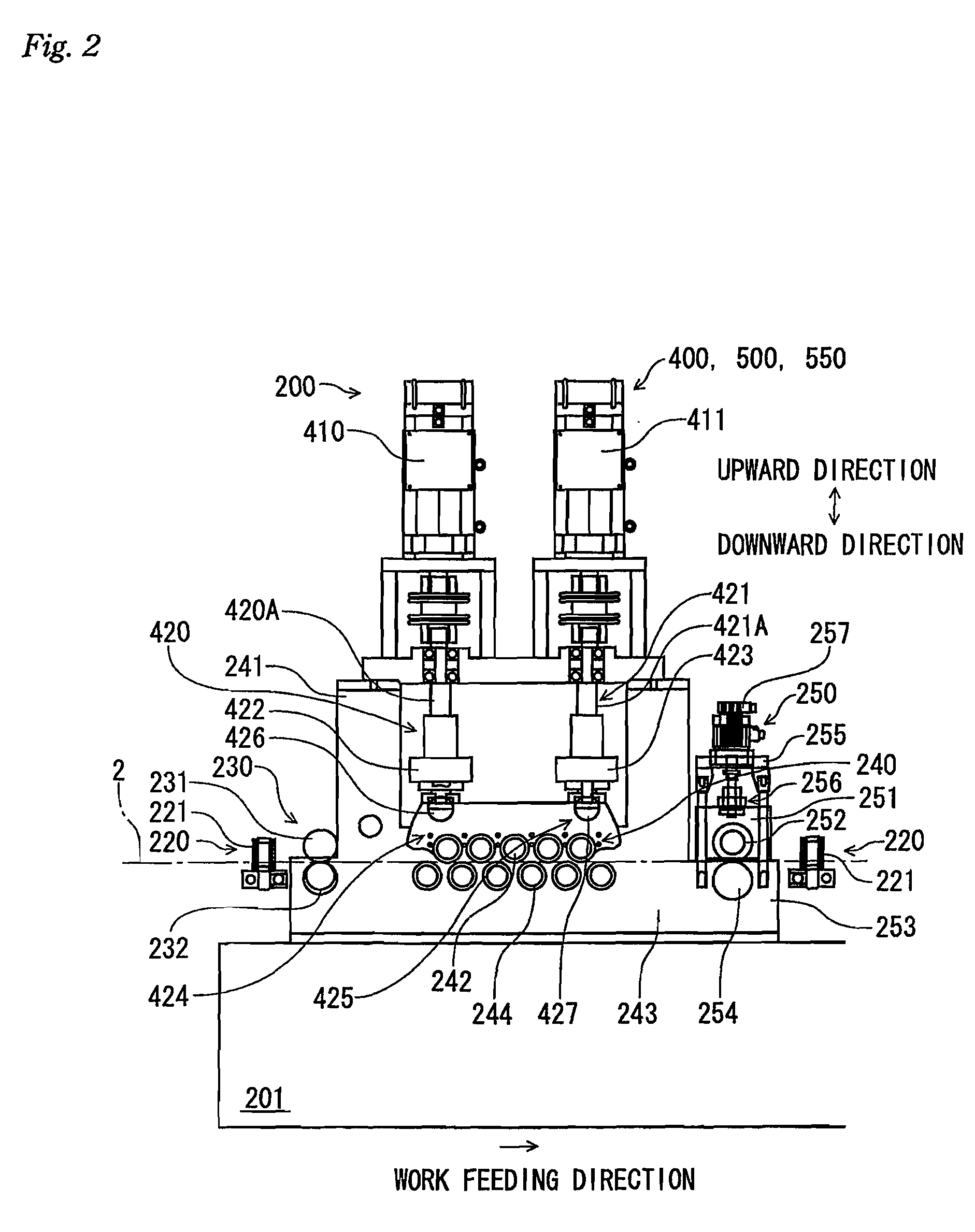
[0049]Referring to FIG. 1, an automatic press apparatus 1 according to an embodiment of the present invention includes an uncoiler portion 100 that passes out a work object 2 wound in a coil configuration to a straightener feeder portion 200 disposed downstream thereof with respect to the flow of the working process, the straightener feeder portion 200 that receives the work object 2 passed out from the uncoiler portion 100 and passes out it to a press portion 300 downstream thereof with respect to the flow of the working process while leveling deformation such as curling of the work object 2 and the press portion 300 that performs press work on the work object 2 passed out from the str...


PUM

PropertyMeasurementUnit
degree of freedomaaaaaaaaaa
distanceaaaaaaaaaa
rotational movementaaaaaaaaaa

Abstract

A release mechanism for use in a leveling apparatus that performs a leveling process on a work object that has been wound in a coil configuration as a result of the work object being passed between a front side work roll in contact with the front side surface of the work object and a back side work roll that is in contact with the back side surface of the work, wherein the releasing mechanism switches between a work clamp state that allows performance of the leveling process and a release state that releases the work object from the clamp state by displacing a work roll support member that supports one of the work rolls relative to the another support member to change a distance between the work rolls by utilizing rotational movement of an electric motor.

Description

FIELD OF THE INVENTION[0001]The present invention relates to a work release mechanism for use in a leveling apparatus (or straightener) for leveling (or correcting) deformation such as winding strain of a work object and to a leveling apparatus equipped with such a release mechanism.BACKGROUND[0002]When a press work is performed, for example, on a work object (e.g. a long metal plate) that has been wound in a coil (or roll) configuration, it is necessary to feed the work object to a press work apparatus at a predetermined (or desired) feed speed (or ratio) while leveling it to eliminate winding strain. To this end, various types of so-called straightener feeders have been developed.[0003]When positioning of the work object is to be performed in a press work apparatus, it is required for the straightener feeder to release clamping of the work object to set it free with respect to the plane of the work object or at least with respect to the work feeding direction, in order to attain p...

Claims


Application Information

Patent Timeline
Patent Type & Authority Applications(United States)
IPC IPC(8): B21B39/02
CPCB21B39/02B21D43/09B21D1/02
Inventor YOSHIOKA, TAKASHI
Owner AIDA ENG LTD
Why Eureka
Try Eureka