Internal combustion engine system

a technology of internal combustion engine and combustion engine, which is applied in the direction of machines/engines, electric control, combustion air/fuel air treatment, etc., can solve the problems of difficult control of ignition timing, and achieve the effect of extending the temperature control rang

Inactive Publication Date: 2008-05-01
HONDA MOTOR CO LTD
View PDF12 Cites 59 Cited by
  • Summary
  • Abstract
  • Description
  • Claims
  • Application Information

AI Technical Summary

Benefits of technology

[0011]In order to overcome the problems, an object of the present invention is to provide an internal combustion engine system switchable between a spark ignition operation and a homogeneous charge compression ignition operation in which the ignition timing of a homogeneous charge compression ignition can be controlled precisely during the homogeneous charge compression ignition operation.

Problems solved by technology

However, as distinct from spark ignition internal combustion engines, homogeneous charge compression ignition internal combustion engines have problems that it is difficult to control ignition timing and the engines can be operated safely only in a narrow operating range.
More specifically, the problems mean that use of a fuel with high ignitability tends to cause knocking when required load of the engine is high, and that use of a fuel with low ignitability tends to cause misfire when required load of the engine is low.

Method used


Image

  • Internal combustion engine system
  • Internal combustion engine system
  • Internal combustion engine system

Examples


Embodiment Construction

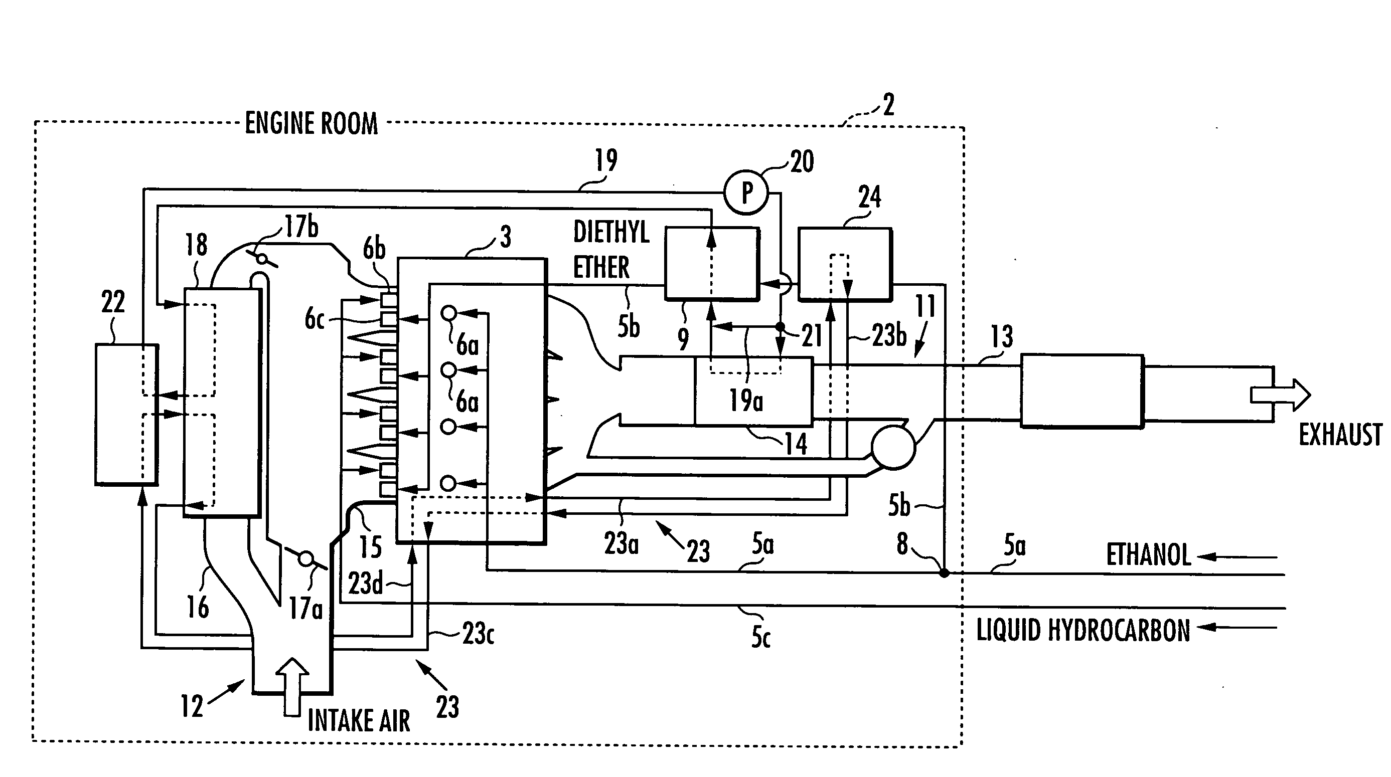
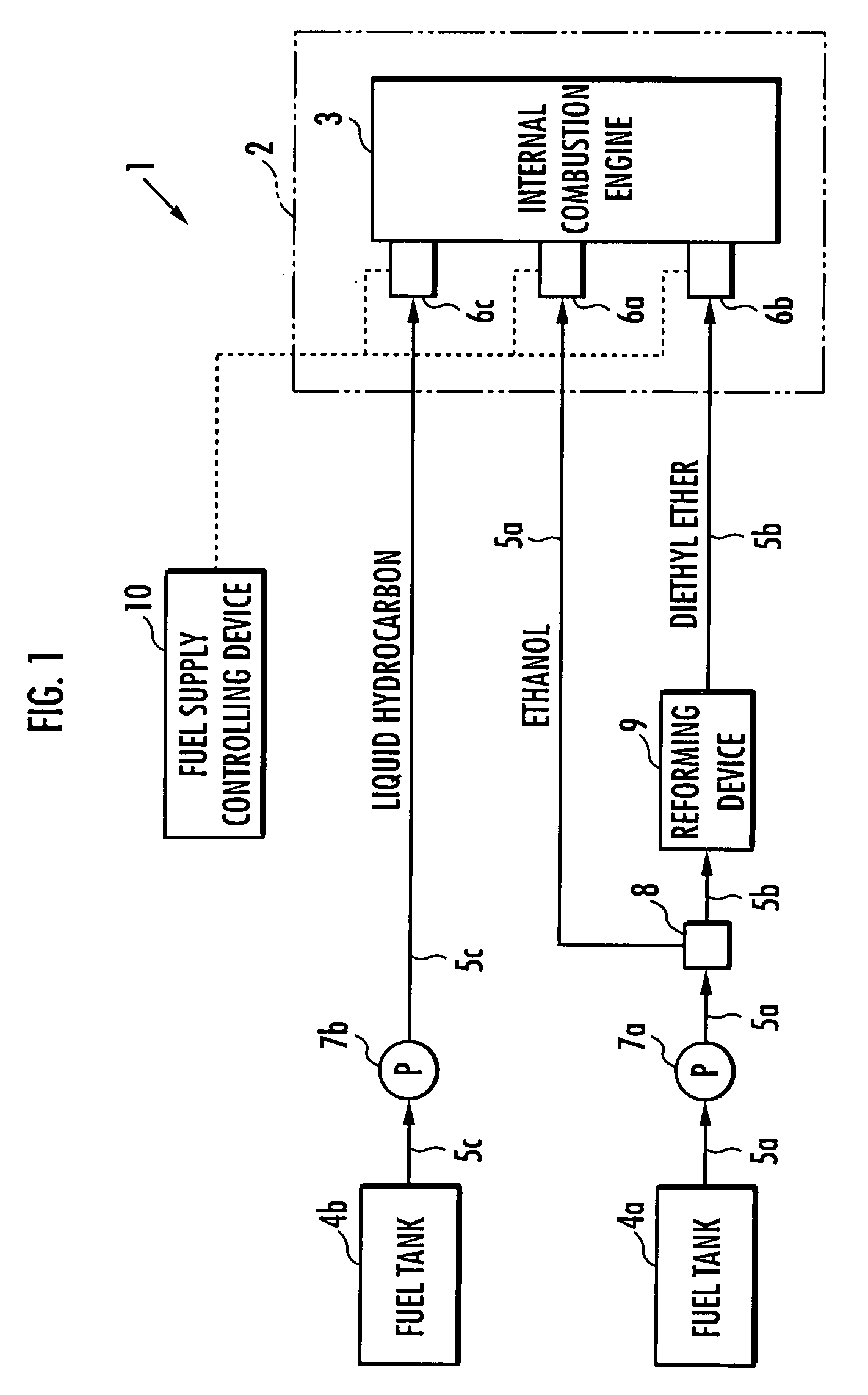
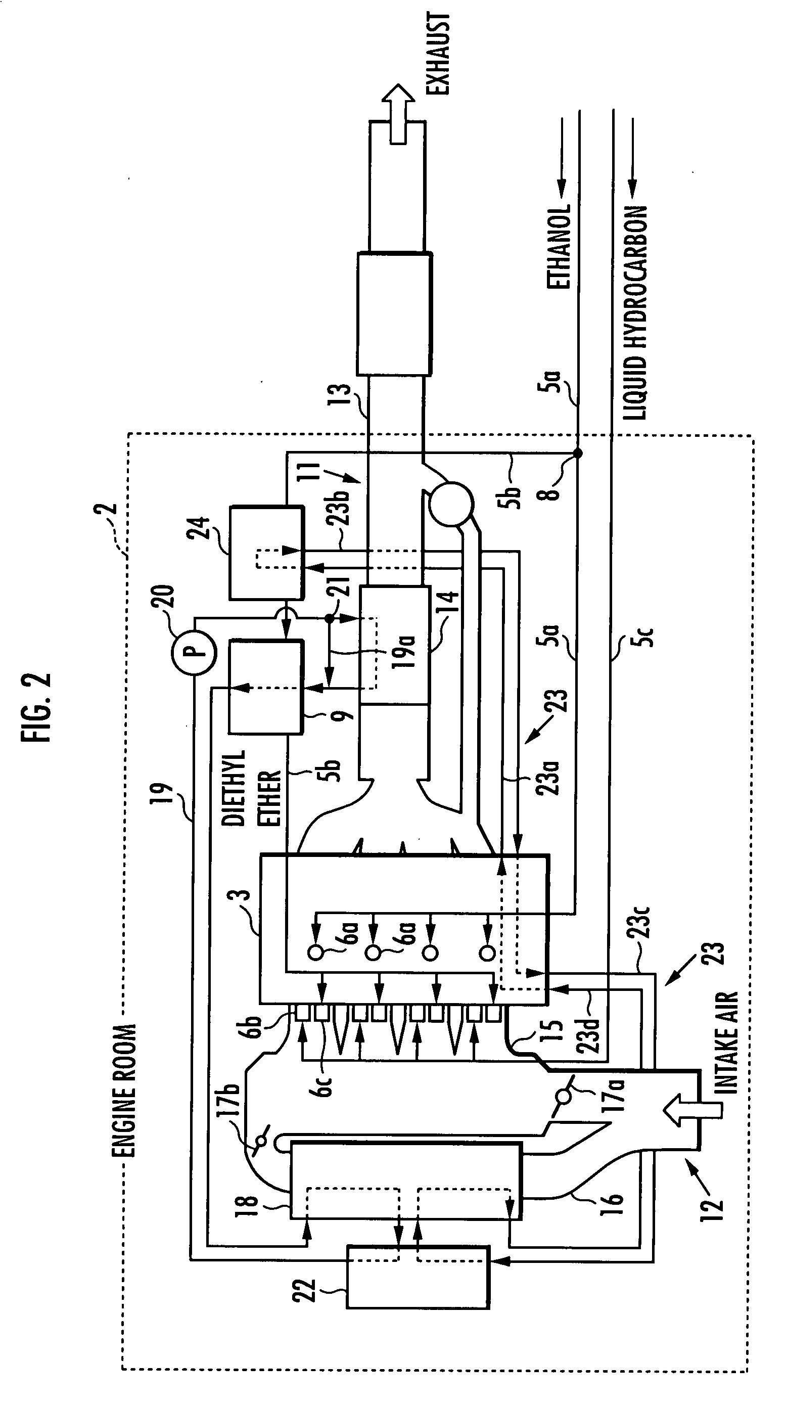
[0036]Hereinafter, embodiments of the present invention will be described in further detail with reference to the attached drawings. FIG. 1 is a system configuration diagram showing a configuration example of the internal combustion engine system according to the present invention. FIG. 2 is a system configuration diagram showing a configuration of an engine room in the internal combustion engine system of FIG. 1. FIGS. 3 and 4 are function explanatory views of functions of a heating medium in the system of FIG. 2. FIG. 5 is a system configuration diagram showing another configuration example of the internal combustion engine system according to the present invention.

[0037]As shown in FIG. 1, an internal combustion engine system 1 according to the present embodiment comprises an internal combustion engine 3 installed in an engine room 2, a first fuel tank 4a and a second fuel tank 4b that provide fuels to the internal combustion engine 3. The internal combustion engine 3 is a hybrid...


PUM


Abstract

The present invention provides an internal combustion engine system that can precisely control ignition timing on homogeneous charge compression ignition. The internal combustion engine system includes a fuel tank 4a containing ethanol, a fuel tank 4b containing at least one of gasoline and GTL naphtha, a reforming device 9 for reforming ethanol to obtain diethyl ether, a heat exchange device 14 for heating a heating medium, an ethanol heater 9b for heating ethanol with the heating medium, and a fuel supply controlling device 10 for controlling a mixture ratio of the fuel. The internal combustion engine system further includes an intake air heater 18 for heating intake air with the heating medium. The internal combustion engine system further comprises an adiabatic storage container 29 for storing the heating medium during a halt of an internal combustion engine 3. The internal combustion engine system further comprises a flow controlling device 27 for flowing the heating medium to the adiabatic storage container 29 only when a temperature detected by a thermal detector 30a is higher than a temperature detected by a thermal detector 30b during an operation of the internal combustion engine 3. The internal combustion engine system further comprises a fuel tank 42 containing a mixed fuel, and a separating device 43 for separating the mixed fuel into an ethanol-water mixture, gasoline and GTL naphtha by adding water to the mixed fuel.

Description

BACKGROUND OF THE INVENTION[0001]1. Field of the Invention[0002]The present invention relates to an internal combustion engine system switchable between a spark ignition operation and a homogeneous charge compression ignition operation.[0003]2. Description of the Related Art[0004]In recent years, in order to improve fuel efficiency and reduce emission matters in internal combustion engines, compression ignition internal combustion engines represented by homogeneous charge compression ignition internal combustion engines have been under review. In a homogeneous charge compression ignition internal combustion engine, oxygen containing gas and a compression ignition fuel are introduced into a cylinder and compressed to ignite spontaneously.[0005]However, as distinct from spark ignition internal combustion engines, homogeneous charge compression ignition internal combustion engines have problems that it is difficult to control ignition timing and the engines can be operated safely only ...

Claims


Application Information

Patent Timeline
Patent Type & Authority Applications(United States)
IPC IPC(8): F02M43/00
CPCF02B1/12F02M25/0224F02D41/0025F02D41/3035F02M25/0228F02M25/10F02M27/02F02M31/18Y02T10/128Y02T10/36F02D19/0628F02D19/0655F02D19/0665F02D19/0671F02D19/0678F02D19/0692F02D19/08Y02T10/12Y02T10/30
Inventor KAMIO, JUNICHI
Owner HONDA MOTOR CO LTD
Why Eureka
Try Eureka