
Reconfigurable reaction wheel for spacecraft

a technology of spacecraft and reaction wheel, which is applied in the direction of vehicle position/course/altitude control, process and machine control, instruments, etc., can solve the problems of increasing the cost of spacecraft development, launch and mission operations, and the difficulty of system engineer designing spacecraft, etc., and achieves the effect of increasing the torque constan

Inactive Publication Date: 2008-05-01
ITHACO SPACE SYST
View PDF16 Cites 18 Cited by
  • Summary
  • Abstract
  • Description
  • Claims
  • Application Information

AI Technical Summary

Benefits of technology

"The present invention is a reconfigurable reaction wheel for spacecraft that includes a motor and a flywheel. The motor is adapted to operate in different electrical configurations, which allows for different levels of torque and the ability to change between them. The motor can be selected from a remote location using electrical circuits or solid state electronic switches. The invention also includes a control system for selecting the motor's operating state and a method of operating the spacecraft using the reconfigurable reaction wheel. The technical effects of the invention include improved spacecraft maneuverability, reduced spacecraft weight, and improved spacecraft efficiency."

Problems solved by technology

With the ever-increasing cost of spacecraft development, launch and mission operations, it is more common to have multiple payloads on one spacecraft bus.
This presents a difficult challenge for a systems engineer designing a spacecraft since each payload generally has a different set of operating requirements.
This approach, by nature, forces the mission planners to collect together on one spacecraft a few payloads with similar operating requirements to avoid defining a mission with such widely varying requirements that it cannot be achieved using a single set of reaction wheel assemblies.
Because of weight considerations, it is rarely, if ever, practical to employ such an arrangement of multiple reaction wheels to provide torque about each direction.
As such, the mission planner is limited in the objectives that may be achieved on a given mission.

Method used


Image

  • Reconfigurable reaction wheel for spacecraft
  • Reconfigurable reaction wheel for spacecraft
  • Reconfigurable reaction wheel for spacecraft

Examples


example 1

Single Mission with Multiple Payloads on One Spacecraft

[0061]With the ever-increasing cost of spacecraft development, launch and mission operations, it is more common to have multiple payloads on one spacecraft bus. This presents a difficult challenge for the systems engineer since each payload generally has a different set of operating requirements. Parameters related to the reaction wheel such as torque, power, momentum storage and management, and disturbances induced on the payload by a spinning reaction wheel are particularly relevant. Traditionally, the systems engineer gathers together the operating requirements for each payload instrument or experiment on the spacecraft and creates a superset of requirements that encompasses all possible operating conditions. Then, these system level requirements are analyzed and flowed down via hardware specifications to the individual bus sensors and actuators such as reaction wheel assemblies. This approach, by nature, forces mission plann...

example 2

Single Mission with Changing Orbit

[0068]There is a continual need for reductions in the cost of space missions. An ever-increasing number of missions are proposed each year. However, the resources to accomplish even a small fraction of the total desired missions are not available. As technologies emerge that allow resources to be stretched further, there is a need to embrace these technologies whenever possible. It is believed that the reconfigurable reaction wheel technology disclosed herein can reduce the costs of some missions and allow previously hard to realize mission objectives to be more easily attained. The following example illustrates how the flexibility of the reconfigurable reaction wheel 100 enables a single spacecraft to perform in two separate orbits.

Sample Mission 2: High Precision Mapping

[0069]Mission Objective: A high precision mapping mission is being planned to a nearby planet to determine the best locations for a large number of remote weather stations. The spa...

example 3

Multiple Missions with Common Bus Design and Rapidly Deployable Spacecraft

[0075]There are some mission applications that require satellite assets to be available at a moment's notice to assist with natural disasters, wars, or other items of safety or national interest. The current strategy is to have multiple satellites in orbit ready to be used when the need arises. It is also common to have spare weather or communications satellites in orbit that are able to replace a failed satellite so that mission objectives can continue with minimal interruption. A large amount of money is expended each year to develop, launch and maintain in orbit this class of quick response satellites and on orbit spares. To this end, a class of satellites is being considered that would be stored in a controlled environment on the ground until they are needed in space. This approach creates different challenges that can also be quite costly but with reduced on-orbit life requirements and reduced orbit maint...


PUM


Abstract

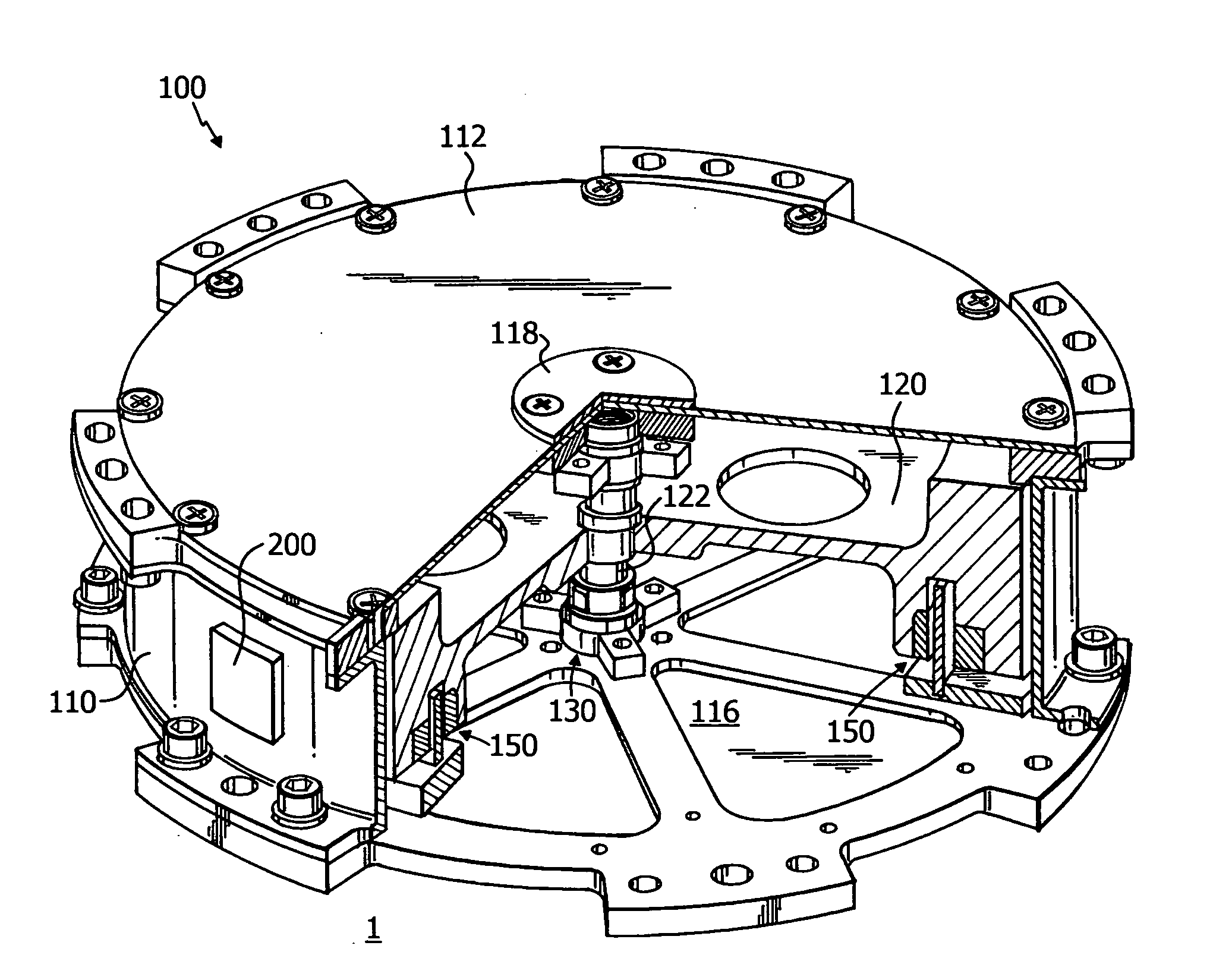
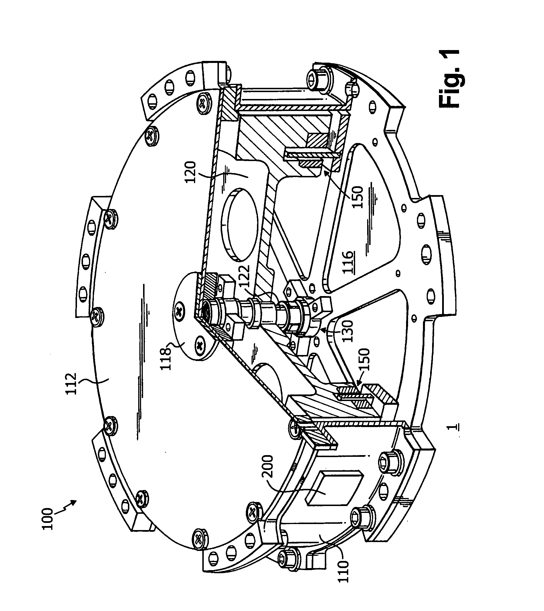
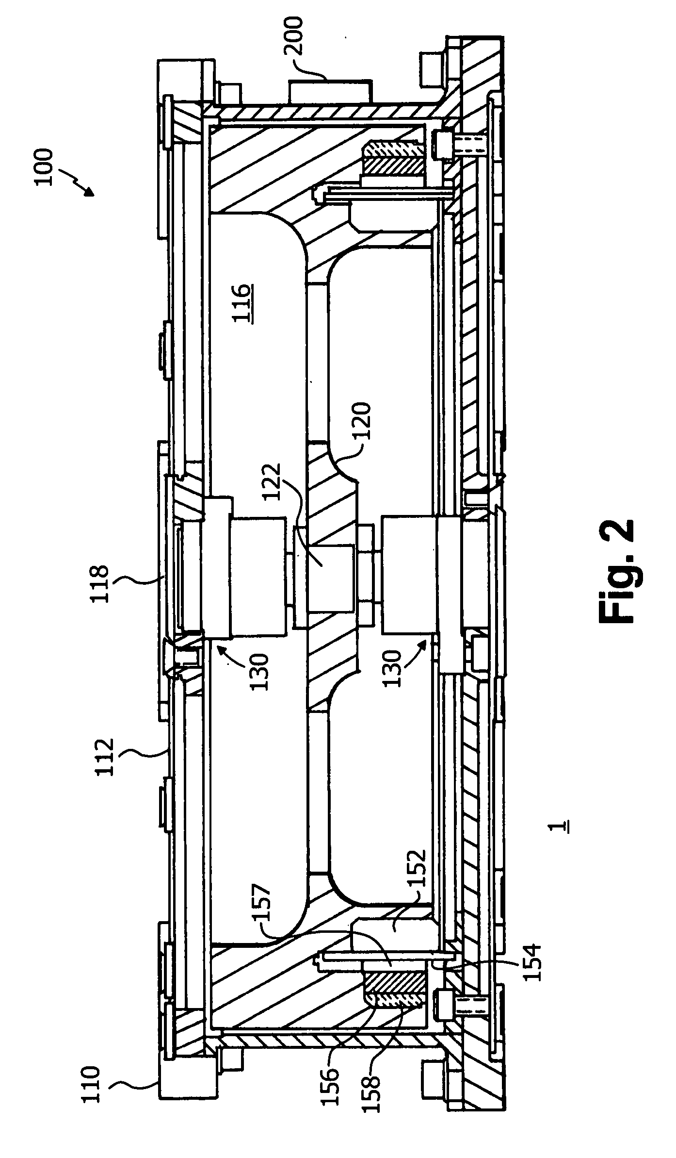
The invention provides a reconfigurable reaction wheel for a spacecraft, a spacecraft, and a method of using the reconfigurable reaction wheel to control the movement of a spacecraft. The reaction wheel includes a reaction wheel housing, a flywheel rotatably disposed in the housing and an electric motor operably coupled to the flywheel. The electric motor includes a plurality of electrical windings. The motor is adapted and configured to operate in a first selectable operating state wherein the windings are arranged in a first electrical configuration, and a second selectable operating state wherein the windings are arranged in a second electrical configuration different from the first electrical configuration.

Description

BACKGROUND OF THE INVENTION[0001]1. Field of the Invention[0002]The present invention relates to a device for stabilizing spacecraft. Particularly, the present invention is directed to a reaction wheel that can operate in a plurality of selectable operating states.[0003]2. Description of Related Art[0004]Spacecraft mission objectives are generally bounded by the capabilities of existing technologies or incremental next-generation technological advances that can be achieved with reasonable development costs. As the state-of-the-art in a particular technology advances, mission objectives and capabilities can be re-examined and possibly redefined to take advantage of those advances.[0005]A reaction wheel is a type of flywheel used primarily by spacecraft to change their angular momentum without using fuel for rockets or other reaction devices. They increase the pointing precision and reliability of a spacecraft, and may also reduce the mass fraction needed for fuel. Spin-up and braking...

Claims


Application Information

Patent Timeline
Patent Type & Authority Applications(United States)
IPC IPC(8): B64G1/28
CPCG05D1/0883B64G1/283B64G1/244
Inventor BIALKE, WILLIAM E.
Owner ITHACO SPACE SYST
Learn More